Resources

Concrete Masonry Veneers

INTRODUCTION

In addition to its structural use or as the exterior wythe of composite and noncomposite walls, concrete brick and architectural facing units are also used as veneer over various backing surfaces. The variety of surface textures, colors, and patterns available makes concrete masonry a versatile and popular exterior facing material. Architectural units such as split-face, scored, fluted, ground face, and slump are available in a variety of colors and sizes to complement virtually any architectural style.

VENEER—DESIGN CONSIDERATIONS

Veneer is a nonstructural facing of brick, stone, concrete masonry or other masonry material securely attached to a wall or backing. Veneers provide the exterior wall finish and transfer out-of-plane loads directly to the backing, but they are not considered to add to the load-resisting capacity of the wall system. Backing material may be masonry, concrete, wood studs or steel studs.

There are basically two types of veneer—anchored veneer and adhered veneer. They differ by the method used to attach the veneer to the backing, as illustrated in Figure 1. Unless otherwise noted, veneer requirements are those contained in the International Building Code (IBC) and Building Code Requirements for Masonry Structures (refs. 2, 3).

For the purposes of design, veneer is assumed to support no load other than its own weight. The backing must be designed to support the lateral and in some instances the vertical loads imposed by the veneer in addition to the design loads on the wall, since it is assumed the veneer does not add to the strength of the wall.

Masonry veneers are typically designed using prescriptive code requirements that have been developed based on judgement and successful performance. The prescriptive requirements relate to size and spacing of anchors and methods of attachment, and are described in the following sections. The assembly can be designed as a noncomposite cavity wall where the out-of-plane loads are distributed to the two wythes in proportion to their relative stiffness. Design criteria are provided in IBC Chapter 16 as well as in TEK 16-04A, Design of Concrete Masonry Noncomposite (Cavity) Walls, (ref. 4).

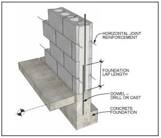
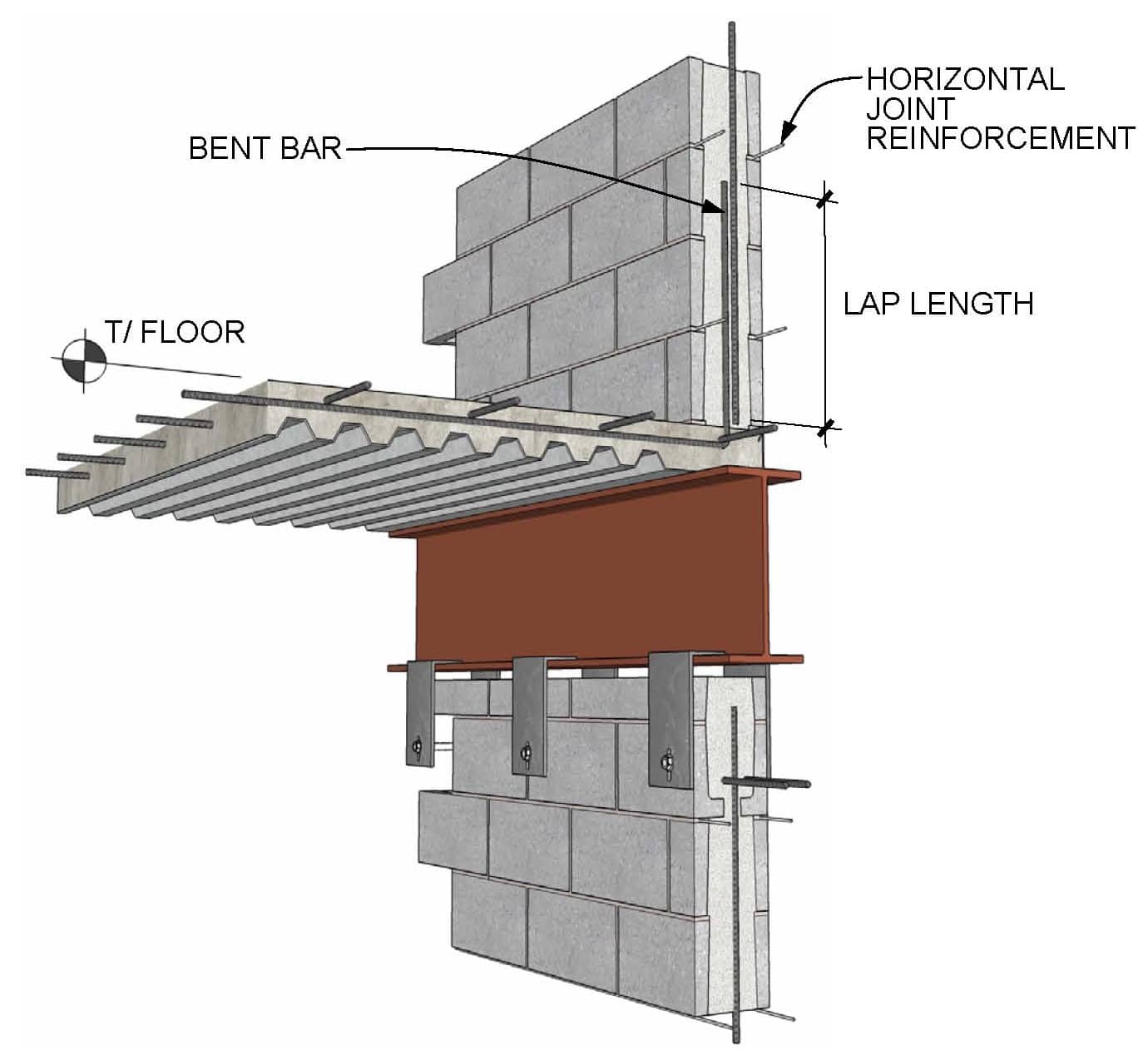
In addition to structural requirements, differential movement between the veneer and its supports must be accommodated. Movement may be caused by temperature changes, moisture-volume changes, or deflection. In concrete masonry, control joints and horizontal joint reinforcement effectively relieve stresses and accommodate small movements. For veneer, control joints should generally be placed in the veneer at the same locations as those in the backing, although recommended control joint spacing can be adjusted up or down based on local experience, the aesthetic requirements of the project, or as required to prevent excessive cracking. See CMU-TEC 009-23, Crack Control for Concrete Brick and Other Concrete Masonry Veneers (ref. 5), for further information.

For exterior veneer, water penetration into the cavity is anticipated. Therefore, the backing system must be designed and detailed to resist water penetration and prevent water from entering the building. Flashing and weeps in the veneer collect any water that penetrates the veneer and redirects it to the exterior. Partially open head joints are one preferred type of weep. They should be at least 1 in. (25 mm) high and spaced not more than 32 in. (813 mm) on center. If necessary, insects can be thwarted by inserting stainless steel wool into the opening or by using proprietary screens. For anchored veneer, open weeps can also serve as vents, allowing air circulation in the cavity to speed the rate of drying. Additional vents may be installed at the tops of walls to further increase air circulation. More detailed information is contained in TEK 05-01B, Concrete Masonry Veneer Details, TEK 19-04A, Flashing Strategies for Concrete Masonry Walls, and TEK 19-05A, Flashing Details for Concrete Masonry Walls (refs. 1, 6, 7).

ANCHORED VENEER

Anchored veneer is veneer which is supported laterally by the backing and supported vertically by the foundation or other structural elements. Anchors are used to secure the veneer and to transfer loads to the backing. Anchors and supports must be noncombustible and corrosion-resistant.

The following prescriptive criteria apply to anchored veneer in areas with velocity pressures, qz, up to 40 psf (1.92 kPa). Modified prescriptive criteria is available for areas with qz greater than 40 psf (1.92 kPa) but not exceeding 55 psf (2.63 kPa) with a building mean roof height up to 60 ft (18.3 m). These modified provisions are presented in the section High Wind Areas. In areas where qz exceeds 55 psf (2.63 kPa), the veneer must be designed using engineering philosophies, and the following prescriptive requirements may not be used.

In areas where seismic activity is a factor, anchored veneer and its attachments must meet additional requirements to assure adequate performance in the event of an earthquake. See the section Seismic Design Categories C and Higher for details.

Masonry units used for anchored veneer must be at least 2 in. (67 mm) thick.

A 1 in. (25 mm) minimum air space must be maintained between the anchored veneer and backing to facilitate drainage. A 1 in. (25 mm) air space is considered appropriate if special precautions are taken to keep the air space clean (such as beveling the mortar bed away from the cavity). Otherwise, a 2 in. (51 mm) air space is preferred. As an alternative, proprietary insulating drainage products can be used.

The maximum distance between the inside face of the veneer and the outside face of the backing is limited to 4 ½ in. (114 mm), except for corrugated anchors used with wood backing, where the maximum distance is 1 in. (25 mm).

When anchored veneer is used as an interior finish supported on wood framing, the veneer weight is limited to 40 lb/ft2 (195 kg/m2).
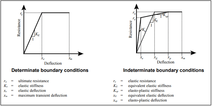
Deflection Criteria

Deflection of the backing should be considered when using masonry veneer, in order to control crack width in the veneer and provide veneer stability. This is primarily a concern when masonry veneer is used over a wood or steel stud backing. Building Code Requirements for Masonry Structures, however, does not prescribe a deflection limit for the backing. Rather, the commentary presents various recommendations for deflection limits.

For anchored veneer, Chapter 16 of the International Building Code requires a deflection limit of l/240 for exterior walls and interior partitions with masonry veneer.

Support of Anchored Veneer

The height and length of the veneered area is typically not limited by building code requirements. The exception is when anchored veneer is applied over frame construction. For wood stud backup, veneer height is limited to 30 ft (9.14 m) (height at plate) or 38 ft (11.58 m) (height at gable). Similarly, masonry veneer over steel stud backing must be supported by steel shelf angles or other noncombustible construction for each story above the first 30 ft (9.14 m) (height at plate) or 38 ft (11.58 m) (height at gable). This support does not necessarily have to occur at the floor height, for example it can be provided at a window head or other convenient location.

Exterior anchored veneer is permitted to be supported on wood construction under the following conditions:

  • the veneer has an installed weight of 40 psf (195 kg/m2) or less,
  • the veneer has a maximum height of 12 ft (3.7 m),
  • a vertical movement joint in the veneer is used to isolate the veneer supported on wood construction from that supported by the foundation,
  • masonry is designed and constructed so that the masonry is not in direct contact with the wood, and
  • the horizontally spanning member supporting the masonry veneer is designed to limit deflection due to unfactored dead plus live loads to l/600 or 0.3 in. (7.5 mm).

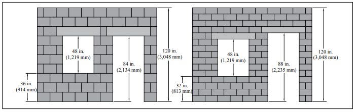
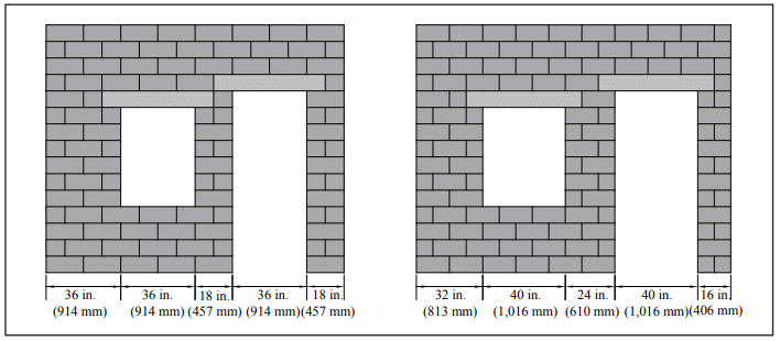
Over openings, the veneer must be supported by non- combustible lintels or supports attached to noncombustible framing, as shown in Figure 2.

The following requirements assume that the veneer is laid in running bond. When other bond patterns are used, the veneer is required to have joint reinforcement spaced no more than 18 in. (457 mm) on center vertically. The joint reinforcement need only be one wire, with a minimum size of W1.7 (MW11).
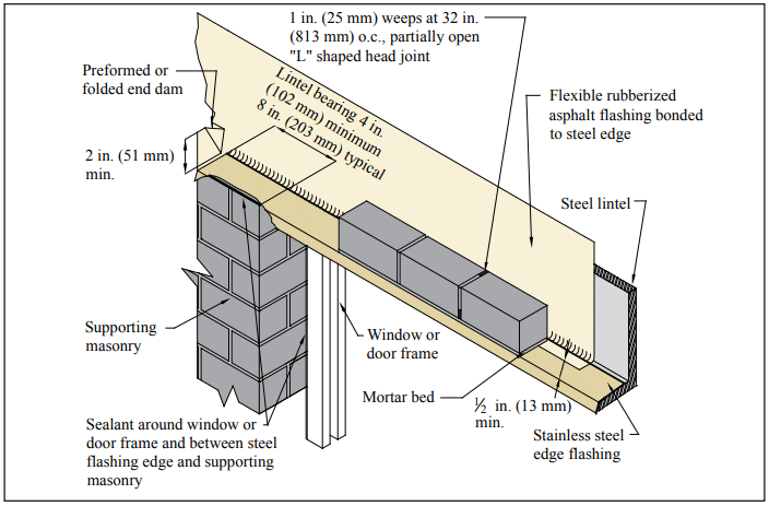
Anchors

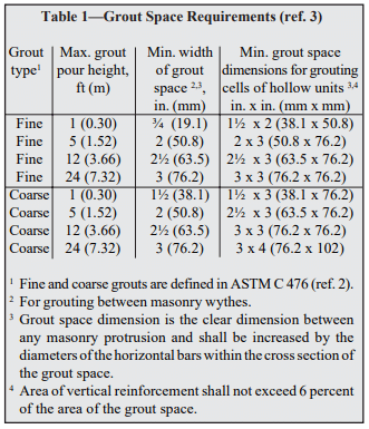
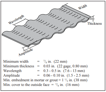
Veneers may generally be anchored to the backing using sheet metal anchors, wire anchors, joint reinforcement or adjustable anchors, although building codes may restrict the use of some anchors. Corrugated sheet metal anchors are permitted with masonry veneer attached to wood backing only. Requirements for the most common anchor types are summarized in Figures 3 through 5 and Table 1. As an alternative, adjustable anchors of equivalent strength and stiffness may be used. Cavity drips are not permitted. See TEK 12-01B, Anchors and Ties for Masonry, (ref. 9) for detailed information on anchor materials and requirements.

Attachment to Backing

When masonry veneer is anchored to wood backing, each anchor is attached to the backing with a corrosion- resistant 8d common nail, or a fastener with equivalent or greater pullout strength. For proper fastening of corrugated sheet metal anchors, the nail or fastener must be located within ½ in. (13 mm) of the 90° bend in the anchor. The exterior sheathing must be either water resistant with taped joints or be protected with a water- resistant membrane, such as building paper ship-lapped a minimum of 6 in. (152 mm) at seams, to protect the backing from any water which may penetrate the veneer.

When masonry veneer is anchored to steel backing, adjustable anchors must be used to attach the veneer. Each anchor is attached with corrosion-resistant screws that have a minimum nominal shank diameter of 0.19 in. (4.8 mm), or an anchor with equivalent pullout strength. Cold-formed steel framing must be corrosion resistant and should have a minimum base metal thickness of 0.043 in. (1.1 mm). Sheathing requirements are the same as those for wood stud backing.

Masonry veneer anchored to masonry backing may be attached using wire anchors, adjustable anchors or joint reinforcement. Veneer anchored to a concrete backing must be attached with adjustable anchors.
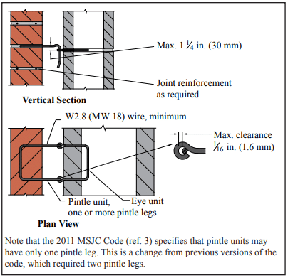
Anchor Placement

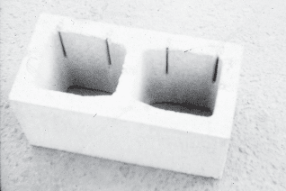
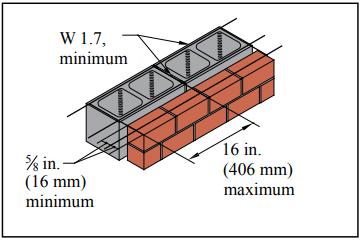
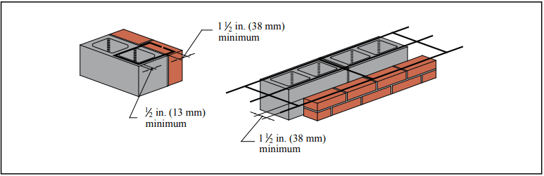
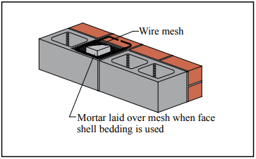
When typical ties and anchors are properly embedded in mortar or grout, mortar pullout or pushout will not usually be the controlling mode of failure. For this reason, connectors must be embedded at least 1 ½ in. (38 mm) into a mortar bed of solid units, and the mortar bed joint must be at least twice the thickness of the embedded anchor. The required embedment of unit ties in hollow masonry is such that the tie must extend completely across the hollow units (Figure 6). Proper embedment can be easily attained with the use of prefabricated assemblies of joint reinforcement and unit ties. Because of the magnitude of loads on anchors, it is recommended that they be embedded in filled cores of hollow units. To save mortar, screens can be placed under the anchor and 1 to 2 in. (25 to 51 mm) of mortar can be built up into the core of the block above the anchor (Figure 7).

High Wind Areas

In areas with qz greater than 40 psf (1.92 kPa) but not exceeding 55 psf (2.63 kPa) with a building mean roof height up to 60 ft (18.3 m), the following modified prescriptive provisions may be used.

The modified prescriptive provisions are:

  • the maximum wall area supported by each anchor must be reduced to 70% of the value listed in Table 1,
  • anchor spacing is reduced to a maximum of 18 in. (457 mm), both vertically and horizontally, and
  • around openings larger than 16 in. (406 mm) in either direction, anchors must be placed within 12 in. (305 mm) of the opening and spaced at 24 in. (610 mm) on center or less.

In areas where qz exceeds 55 psf (2.63 kPa), the veneer must be designed using engineering philosophies.

Seismic Design Categories C and Higher

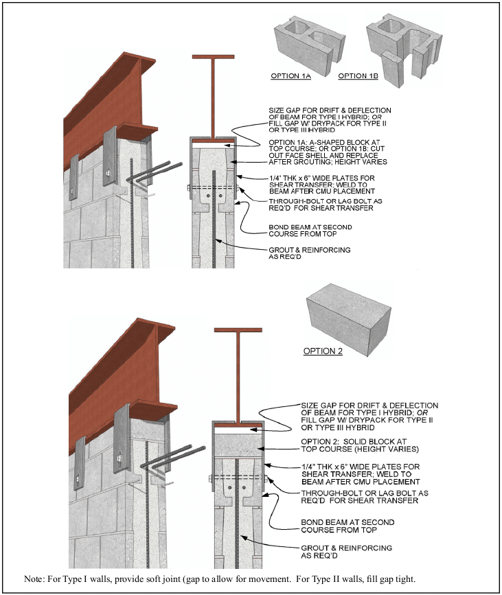
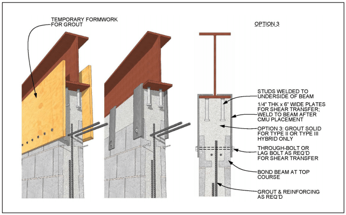
To improve veneer performance under seismic loading in Seismic Design Category (SDC) C, the sides and top of the veneer must be isolated from the structure, so that vertical and lateral seismic forces are not transferred to the veneer. This reduces accidental loading and allows more building deflection without causing damage to the veneer.

In SDC D, in addition to this isolation, the maximum wall area supported by each anchor must be reduced to 75% of the value listed in Table 1, although the maximum spacings are unchanged. In addition, when the veneer is anchored to wood backing, the veneer anchor must be attached to the wood using a corrosion-resistant 8d ring-shank nail, a No. 10 corrosion- resistant screw with a minimum nominal shank diameter of 0.190 in. (4.8 mm), or with a fastener having equivalent or greater pullout strength.

In SDC E and F, the requirements listed above for SDC C and D must be met, as well as the additional requirements listed here. The weight of each story of anchored veneer must be supported independently of other stories to help limit the size of potentially damaged areas. In addition, to improve veneer ductility the veneer must have continuous W1.7 (MW11) single wire joint reinforcement at 18 in. (457 mm) o.c. or less vertically, with a mechanical attachment to the anchors, such as clips or hooks.

ADHERED VENEER

Conventional adhered veneer is veneer secured and supported through adhesion with a bonding material applied over a backing that both meets required deflection limits and provides for necessary adhesion. When applied to a masonry or concrete backing, the veneer may be applied directly to the backing substrate using layers of neat cement paste and Type S mortar, as illustrated in Figure 1. When applied over steel or wood framing, the adhered masonry veneer is applied to a metal lath and portland cement plaster backing placed against the sheathing element and attached to the stud framing members.

Alternative design of adhered veneer is permitted under the International Building Code when in compliance with Building Code Requirements for Masonry Structures (MSJC), where the requirements of unit adhesion (shear stress > 50 psi, 345 kPa) are met, out-of-plane curvature of the backing is limited to prevent the veneer from separating from the backing, and freeze thaw cycling, water penetration, and air and water vapor transmission are considered. Although the MSJC does not stipulate a deflection limit to control out-of-plane curvature, the Tile Council of America limits the deflection of backing supporting ceramic tiles to l/360 (ref. 11). Similarly, IBC Chapter 16 (for engineered design) requires a deflection limit of l/360 for exterior walls and interior partitions with plaster or stucco, which would be similar to an adhered veneer application.

Proprietary polymer-fortified adhesive mortars exist that meet the adhesion requirements and are used as a mortar setting bed to adhere the masonry veneers directly to a masonry or concrete backing, or to a lath and plaster backing system over wood or steel studs.

In addition, several proprietary systems are available to aid in placement of adhered masonry veneer on suitable exterior or interior substrates. These typically take the form of galvanized steel support panels that are mechanically anchored to a masonry or concrete backing, or placed against the sheathing element and attached to stud framing members. These products essentially take the place of the metal lath in the adhered veneer application. The metal panels contain support tabs and other features to facilitate the veneer application, carry the dead load of the veneer, and improve bonding of the veneer to the panel. In some cases, metal panel systems provide drainage or air flow channels as well. In lieu of mortar, construction adhesives having a shear bond strength greater than 50 psi (345 kPa) are used to bond the masonry veneer to the panel and masonry pointing mortar is used to fill the joint space between the masonry units. Installation using these products should follow manufacturer’s instructions.

Masonry units used in this application are limited to 2 in. (67 mm) thickness, 36 in. (914 mm) in any face dimension, 5 ft2 (0.46 m2) in total face area and 15 lb/ft2 (73 kg/m2 ) weight. In addition, the International Building Code (ref. 4) stipulates: a minimum thickness of 0.25 in. (6.3 mm) for weather-exposed adhered masonry veneer; and, for adhered masonry veneers 2 used on interior walls, a maximum weight of 20 lb/ft2 (97 kg/ m2).

When an interior adhered veneer is supported by wood construction, the wood supporting member must be designed for a maximum deflection of 1/600 of its span.

Adhered veneer and its backing must also be designed to either:

  • have sufficient bond to withstand a shearing stress of 50 psi (345 kPa) based on the gross unit surface area when tested in accordance with ASTM C482, Standard Test Method for Bond Strength of Ceramic Tile to Portland Cement Paste (ref. 10), or
  • be installed according to the following:
    • A paste of neat portland cement is brushed on the backing and on the back of the veneer unit immediately prior to applying the mortar coat. This neat cement coating provides a good bonding surface for the mortar.
    • Type S mortar is then applied to the backing and to each veneer unit in a layer slightly thicker than in. (9.5 mm). Sufficient mortar should be used so that a slight excess is forced out the edges of the units.
    • The units are then tapped into place to eliminate voids between the units and the backing which could reduce bond. The resulting thickness of mortar between the backing and veneer must be between and ¼ in. (9.5 and 32 mm).
    • Mortar joints are tooled with a round jointer when the mortar is thumbprint hard.

When applied to exterior stud walls, the IBC requires adhered masonry veneer to include a screed or flashing at the foundation. In addition, minimum clearances must be maintained between the bottom of the adhered veneer and paved areas, adjacent walking surfaces and the earth.

Backing materials for adhered veneer must be continuous and moisture-resistant (wood or steel frame backing with adhered veneer must be backed with a solid water repellent sheathing). Backing may be masonry, concrete, metal lath and portland cement plaster applied to masonry, concrete, steel framing or wood framing. Note that care must be taken to limit deflection of the backing, which can cause veneer cracking or loss of adhesion, when adhered masonry veneer is used on steel frame or wood frame backing. The surface of the backing material must be capable of securing and supporting the imposed loads of the veneer. Materials that affect bond, such as dirt, grease, oil, or paint (except portland cement paint) need to be cleaned off the backing surface prior to adhering the veneer.

NOTATIONS:

l = clear span between supports, in. (mm)

qz = velocity pressure evaluated at height z above ground, in.-lb/ft2 (kPa)

REFERENCES

  1. Concrete Masonry Veneer Details, TEK 05-01B. Concrete Masonry & Hardscapes Association, 2003.
  2. 2012 International Building Code. International Code Council, 2012.
  3. Building Code Requirements for Masonry Structures, ACI 530-11/ASCE 5-11/TMS 402-11. Reported by the Masonry Standards Joint Committee, 2011.
  4. Design of Concrete Masonry Noncomposite (Cavity) Walls, TEK 16-04A. Concrete Masonry & Hardscapes Association, 2004.
  5. Crack Control Strategies for Concrete Masonry Construction, CMU-TEC-009-23, Concrete Masonry & Hardscapes Association, 2023.
  6. Flashing Strategies for Concrete Masonry Walls, TEK 1904A. Concrete Masonry & Hardscapes Association, 2008.
  7. Flashing Details for Concrete Masonry Walls, TEK 19-05A. Concrete Masonry & Hardscapes Association, 2008. 
  8. McMican, Donald G. Is Flashing Dangerous Without a Drip? The Aberdeen Group, 1999.
  9. Anchors and Ties for Masonry, TEK 12-01B. Concrete Masonry & Hardscapes Association, 2011.
  10. Standard Test Method for Bond Strength of Ceramic Tile to Portland Cement Paste, ASTM C482-02(2009). ASTM International, 2009.
  11. Handbook for Ceramic Tile Installation. Tile Council of America, 1996.

Surface Bonded Concrete Masonry Construction

INTRODUCTION

Surface bonding is an economical construction technique which was first introduced in the late sixties by the U. S. Department of Agriculture for use in low cost housing. In surface bonded construction, concrete masonry units are laid dry and stacked, without mortar, to form walls. Walls are constructed with units that have been precision ground or honed to achieve a uniform bearing surface, or with shims placed periodically to maintain a level and plumb condition. Both sides of the wall are then coated with a thin layer of reinforced surface bonding mortar. The synthetic fibers which reinforce the surface bonding mortar impart a tensile strength of about 1500 psi (10.3 MPa), producing a strong wall despite the relatively thin thickness of material on each side. The surface coating on each side of the wall bonds the concrete masonry units together in a strong composite construction, and serves as a protective water resistant shield.

Surface bonded concrete masonry has a number of advantages:

  • Less time and skill are required for wall construction. In a 1972 study of mason productivity sponsored by the U. S. Department of Housing and Urban Development and other interested organizations, it was found that surface bonded concrete masonry construction resulted in 70 percent greater productivity than that achievable with conventional construction.
  • The surface bonding mortar provides excellent resistance to water penetration in addition to its function of holding the units together. Tests of surface bonded walls have repeatedly shown their resistance to wind driven rain to be “excellent” even with wind velocities as great as 100 mph (161 km/h), and over test periods of 8 hours.
  • Colored pigment can be incorporated into the surface bonding mortar to produce a finished surface without the need to paint.

Surface bonded concrete masonry construction offers all of the benefits and advantages of conventional concrete masonry construction, such as:

  • fire safety
  • acoustic insulation
  • energy efficiency
  • lasting durability and beauty

DESIGN STRENGTH

Many structural and nonstructural tests have been performed on surface bonded walls to establish design parameters for the system.

The nonstructural properties, such as sound transmission class, fire resistance period, and energy efficiency, of surface bonded concrete masonry can be considered equivalent to a conventional mortared concrete masonry wall.

There are a few differences between the structural properties of the two types of construction. These differences are discussed in the following paragraphs, and are illustrated in Figure 1 for ungrouted, unreinforced walls. Although national building codes, such as the BOCA National Building Code and the Standard Building Code (refs. 1, 3) do not specifically address reinforced or grouted surface bonded walls, manufacturers of surface bonding mortars may have code-approved criteria for their products.

Compressive Loads

Resistance to vertical compressive loads depends primarily on the compressive strength of the concrete block used in the wall construction. Stronger units make stronger walls. With mortared construction, a rule of thumb is that the wall strength will generally be about seventy percent of the unit strength. In comparison, surface bonded walls built with unground concrete masonry units develop approximately thirty percent of the strength of the individual block. This reduced wall strength is depicted in Figure 1 for walls constructed with unground concrete masonry units.

The lower value obtained with the unground units is due to a lack of solid bearing contact between units, due to the natural roughness of the concrete units. The mortar bed used in conventional construction compensates for this roughness and provides a uniform bearing between units. If the masonry unit bearing surfaces are ground flat and smooth before the wall is erected, results similar to those for a mortared wall can be expected. In Figure 1, note that surface bonded walls built with precision ground concrete masonry units are equally as strong in compression as the conventional construction.

Flexural Resistance

The flexural strength of a surface bonded wall is about the same as that of a conventional mortared wall, as shown in Figure 1. When walls are tested in the vertical span (i.e., a horizontal force, such as wind, is applied to a wall that is supported at the top and bottom) surfaced bonded walls and mortared walls have about the same average strength; failure occurs in the surface bonded coating due to tensile stress at or near one of the horizontal joints. With mortared construction, failure occurs at a horizontal joint with bond failure between the mortar and the masonry units. The data from numerous tests on surface bonded constructions led to an allowable stress of 18 psi (0.12 MPa) based on the gross area.

When walls are laid in a running bond pattern, either with mortar joints or with surface bonding, and tested in the horizontal span, (i.e., a wall supported at each end is subjected to a horizontal wind force) the strength in bending depends primarily on the strength of the units. This is due to the interlocking of the masonry units laid when in a running bond configuration. In such tests in the horizontal span, the wall strength of the surface bonded wall is exactly the same as the conventional construction. In Table 1, an allowable flexural stress of 30 psi (0.21 MPa) is recommended for horizontal span when the units have been laid in running bond.

Shear Strength

The shear resistance of surface bonded construction is the same as that of conventional walls. With face shell mortar bedding, conventional concrete masonry walls averaged 42 psi (0.29 MPa) shear resistance, based on gross area. Nine surface bonded walls, 8 in. (203 mm) in thickness, had an average shear resistance of 39 psi (0.27 MPa), and three 6 in. (152 mm) thick surface bonded walls averaged 40 psi (0.28 MPa). These data are compared in Figure 1, and led to a recommended allowable shear stress of 10 psi (0.07 MPa) on the gross area (see Table 1).

Compression:45 psi (0.31 MPa)
Shear:10 psi (0.07 MPa)
Flexural Tension:
Horizontal span:30 psi (0.21 MPa)
Vertical span:18 psi (0.12 MPa)
a References 1 & 3

Table 1—Allowable Stress, Gross Cross-Sectional Area, Dry-Stacked, Surface-Bonded Concrete Masonry Walls

CONSTRUCTION

The construction procedure for surface bonded walls is similar to that of conventional, except that mortar is not placed between the masonry units. Standard Practice for Construction of Dry-Stacked, Surface-Bonded Walls, ASTM C946 (ref. 4), governs the construction methods. Care should be taken to ensure uncoated walls are adequately braced.

Because the walls are constructed without mortar joints, surface bonded wall dimensions do not conform to the standard 4 in. (102 mm) design module. Wall and opening dimensions should be based on actual unit dimensions, which are typically 7 in. high by 15 in. long (194 by 397 mm).

Materials

Surface bonding mortar should comply with Standard Specification for Packaged, Dry, Combined Materials for Surface Bonding Mortar, ASTM C887 (ref. 6), which governs flexural and compressive strength, sampling, and testing. ASTM C946 requires Type I, moisture-controlled, concrete masonry units be used for surface bonded construction. Type I units must be in a dry condition when delivered to the job site. Walls laid using dry units will undergo less drying shrinkage after construction, hence minimizing cracks. Standard Specification for Loadbearing Concrete Masonry Units, ASTM C90 (ref. 5) governs these requirements.

As for mortared masonry construction, materials should be properly stored on site to prevent contamination by rain, ground water, mud, and other materials likely to cause staining or to have other deleterious effects.

If the bearing surfaces of the concrete masonry units are unground, metal or plastic shims or mortar may occasionally be required between units to maintain the wall level and plumb. Shims must have a minimum compressive strength of 2,000 psi (13.8 MPa) to ensure their long term durability after the wall is loaded. Metal shims, if used, should be corrosion resistant to reduce the possibility that they will corrode and bleed through the finished masonry at a later time.

Leveling

Because the footing is not typically level enough to lay up the dry units without additional leveling, the first course of masonry units is laid in a mortar bed or set in the fresh footing concrete to obtain a level base for the remainder of the wall. Vertical head joints should not be mortared, even when the first course is mortar bedded, since mortar in the head joints will misalign the coursing along the wall length.

When required, additional leveling courses are constructed in the wall. Leveling courses should be placed when:

  • the wall is out of level by more than ½ in. (13 mm) in 10 ft,
  • at each floor level, and
  • at a horizontal change in wall thickness (see Figure 2).

After the first course of masonry units is laid level in a mortar bed, dry stacking proceeds with the remaining courses beginning with the corners, and followed by stacking, in running bond, between the corners. As they are dry stacked, the ends of the concrete masonry units should be butted together tightly. Small burrs should be removed prior to placement.

After every fourth course, the wall should be checked for plumb and level.

Crack Control

Temperature and moisture movements have the potential to cause small vertical cracks in a masonry wall. These cracks are an aesthetic, rather than a structural, concern. In exposed concrete masonry, where shrinkage cracks may be objectionable, horizontal joint reinforcement, control joints, or bond beams are used to control cracking. The absence of a mortar bed joint in surface bonded walls means that there is no space in the wall for joint reinforcement, so control joints or bond beams are used for crack control.

Control joints should be placed:

  1. at wall openings and at changes in wall height and thickness
  2. at wall intersections, at pilasters, chases, and recesses
  3. in walls without openings, at intervals of 20 ft (6.1 m) when there are no bond beams in the construction, and at intervals of 60 ft (18.3 m) when bond beams are incorporated every 4 ft (1.2 m) vertically.

Control joints for surface bonded walls are similar to those for mortared concrete masonry. At the control joint location, the surface bonding mortar should be raked out and the joint caulked.

Placing Accessories & Utilities

The absence of a mortar bed joint in the construction also requires that the face shell and/or the cross web of the concrete masonry units be notched or depressed whenever wall ties or anchors must be embedded in the wall. A coarse rasp is typically used to make small notches, while deeper notches are cut with a masonry saw. Cores containing anchors or wall ties should be grouted, or other adequate anchorage should be provided.

Electrical lines and plumbing are often located in the cores of concrete masonry units. These lines should be placed before the surface bonding mortar is applied, so that the masonry units are visible.

Applying Surface Bonding Mortar

Manufacturer’s recommendations should be followed for job site mixing of the premixed surface bonding mortar and application to the dry stacked concrete masonry wall.

As with mortared masonry construction, clean water and mixing equipment should be used to prevent foreign materials from being introduced into the mortar. Batches should be mixed in full bag multiples only, to compensate for any segregation of materials within a bag.

All materials should be mixed for 1 to 3 minutes, until the mixture is creamy, smooth, and easy to apply. Note that mixing time should be kept to a minimum, as overmixing can damage the reinforcing fibers.

The stacked concrete masonry units should be clean and free of any foreign matter which would inhibit bonding of the plaster. Contrary to recommended practice with conventional mortared walls, the dry stacked concrete masonry units should be damp when the surface bonding plaster is applied to prevent water loss from the mortar due to suction of the units. Care should be taken to avoid saturating the units.

It is very important that the surface bonding mortar be applied to both sides of the dry stacked wall since the wall strength and stability depend entirely on this coating.

Premixed surface bonding mortars are smooth textured and easily applied by hand with a trowel. The workability is due to the short ½ in. (13 mm) glass fibers which reinforce the mixture. The mortar should be troweled on smoothly with a minimum thickness of in. (3 mm).

Surface bonding mortar can also be sprayed on. On large projects, use of a power sprayer greatly increases the coverage rate of the mortar and further reduces wall costs. As applied, the “sprayed-on” surface bonding mortar usually has a rougher surface texture than a troweled finish, and possesses slightly less tensile strength due to the lack of fiber orientation in the plane of the mortar coating. This can be overcome by troweling, hand or mechanical, following spray application of the mortar. Hand or mechanical troweling of the sprayed coating also assures that all gaps and crevices are filled.

When a second coat of surface bonding mortar is applied, either by trowel or spray, it should be applied after the first coat is set, but before it is completely hardened or dried out. The second coat may be textured to achieve a variety of finishes.

Joints in surface bonding mortar are weaker than a continuous mortar surface, and, for this reason, should not align with joints between masonry units. If application of the surface bonding mortar is discontinued for more than one hour, the first application should be stopped at least 1 ¼ in. (32 mm) from the horizontal edge of the concrete masonry unit. At the foundation, the surface bonding mortar should either form a cove between the wall and the footer or, for a slab on grade, should extend below the masonry onto the slab edge, as shown in Figure 3. These details help prevent water penetration at the wall/footer interface.

Curing

After surface bonding application, the wall must be properly cured by providing sufficient water for full hydration of the mortar, to ensure full strength development. The wall should be dampened with a water mist between 8 and 24 hours after surface bonding mortar application. In addition, the wall should be fog sprayed twice within the first 24 hours, although with pigmented mortar, this may be extended to 48 hours.

The recommendations above may need to be modified for either cold or hot weather conditions. For example, dry, warm, windy weather accelerates the water evaporation from the mortarrequiring more frequent fog spraying.

At the end of the day, tops of walls should be covered to prevent moisture from entering the wall until the top is permanently protected. Typically, a tarp is placed over the wall, extending at least 2 ft (0.6 m) down both sides of the wall, and weighted down with lumber or masonry units.

REFERENCES

  1. BOCA National Building Code. Country Club Hills, IL: Building Officials and Code Administrators International, Inc. (BOCA), 1996.
  2. Building Code Requirements for Masonry Structures, ACI 530-95/ASCE 5-95/TMS 402-95. Reported by the Masonry Standards Joint Committee, 1995.
  3. Standard Building Code. Birmingham, AL: Southern Building Code Congress International, Inc. (SBCCI), 1997.
  4. Standard Practice for Construction for Dry-Stacked, Surface-Bonded Walls, ASTM C946-91 (1996)e1. American Society for Testing and Materials, 1996.
  5. Standard Specification for Loadbearing Concrete Masonry Units, ASTM C90-97. American Society for Testing and Materials, 1997.
  6. Standard Specification for Packaged, Dry, Combined Materials for Surface Bonding Mortar, ASTM C887-79a (1996)e1 American Society for Testing and Materials, 1996.

Bracing Concrete Masonry Walls Under Construction

INTRODUCTION

Building codes typically place responsibility for providing a reasonable level of life safety for workers during construction on the erecting contractor. Various methods are employed to protect workers while newly constructed masonry walls are curing and/or until the roof or other structural supports are in place. This TEK provides guidelines for masonry wall stability to resist the lateral loading effects of wind during construction. It is based on principles set forth in the Council for Masonry Wall Bracing’s Standard Practice for Bracing Masonry Walls Under Construction (ref. 1), but has been updated in accordance with the design provisions of the 2011 Building Code Requirements for Masonry Structures (MSJC, ref. 2).

When other lateral loads such as impact, seismic, scaffolding, and lateral earth pressure are present, they need to be considered and evaluated separately. The Walls Subject to Backfilling section at the end of this TEK discusses bracing and support of basement walls during backfilling operations.

WALLS SUBJECT TO WIND LOADS

There are several strategies and considerations for protecting life safety on the jobsite. These include internal bracing, external bracing and evacuation zones. The combination of strategies appropriate for a particular job may depend on the type of masonry construction, masonry wall heights, the time elapsed since construction, and wind speeds at the site.

The industry term “internal bracing” is relatively new. Internal bracing refers to the stability of a masonry assembly to resist wind loads through self-weight and allowable flexural stresses within the masonry.

The use of evacuation zones recognizes that it may be impractical to prevent the collapse of a masonry wall during construction when subjected to extreme loading conditions and that life safety is the primary concern. At prescribed wind speeds (taken as three-second gusts measured at the job site), the wall and the area around it is evacuated. The critical wind speed resulting in evacuation depends on the age of the wall being constructed and involves the three terms: “restricted zone,” “initial period,” and “intermediate period.”

Restricted Zone

The restricted zone is the area on each side of a wall subject to the effect of a masonry wall collapse. It is defined by a length equal to the height of the constructed wall plus 4 ft (1.22 m) on both sides of the wall, and a width equal to the wall length plus 4 ft (1.22 m) on both ends of the wall, as shown in Figure 1. When wind speeds exceed those allowed during the initial and intermediate periods, there is a chance that the masonry wall could fail, and the restricted zone must be evacuated in order to ensure life safety.

Initial Period

The initial period is the period of time, not to exceed 24 hours, during which the masonry is being laid above its base or highest line of bracing, and at the end of which required bracing is installed. During this period, the mortar is assumed to have no strength and wall stability is accomplished from the masonry self-weight only. Based on this assumption and a wind speed limit of 20 mph (8.9 m/s), walls can be built to the heights shown in Table 1 without bracing during the initial period. If wind speeds exceed 20 mph (8.9 m/s) during the initial period, work on the wall must cease and the restricted zone on both sides of the wall must be evacuated. Evacuation for walls up to 8 ft (2.44 m) above grade is not necessary until wind speeds reach 35 mph (15.6 m/s) in keeping with a long-standing OSHA requirement.

Intermediate Period

The intermediate period is the period of time following the initial period but before the wall is connected to the elements that provide its final lateral support. The design wind speed is 40 mph (17.9 m/s) 3-second gust for brace design. When the wind speed exceeds 35 mph (15.6 m/s), the restricted zone must be evacuated. The difference of 5 mph (2.2 m/s) is to allow workers time to evacuate the area.

During the intermediate period, the masonry is assumed to have one-half of its design compressive strength and plain masonry allowable flexural stresses are taken as two-thirds of the design value given in the 2011 MSJC (ref. 2). The masonry structural capacity then can be determined using these reduced values in accordance with the provisions of the Code (see ref. 3 for more information).

There are several methods of providing an acceptable level of life safety for masons and others working on the construction site. They are:

  1. bracing to a design wind speed of 40 mph (17.9 m/s), 3-second gust and evacuating if the wind speed exceeds 35 mph (15.6 m/s), 3-second gust,
  2. alternative bracing designs and methods approved, sealed, and signed by a registered professional engineer if supported by data representing field conditions, and
  3. an early warning and evacuation program when the masonry is designed to resist a wind speed of 5 mph (2.2 m/s) greater than the designated evacuation wind speed. The wind speed measurement must be made by an instrument with a ± 2 mph (0.89 m/s) accuracy.

Traditionally, bracing and evacuation of the restricted zones has also been based on wind speeds lower that 35 mph (15.6 m/s). As such, Table 2 addresses evacuation wind speeds of 15 and 25 mph (6.7 and 11.2 m/s) in addition to the 35 mph (15.6 m/s) evacuation wind speed. Many jurisdictions will accept the lower wind speed criteria but users should first confirm acceptability with their local building official and/or OSHA representative before using them.

Table 2 lists maximum unbraced wall heights when early warning with an evacuation program is implemented. Design wind speeds for the heights in Table 2 are for 5 mph (2.2 m/s) greater than the evacuation speed to allow time for the masons to get off the scaffolding and evacuate the restricted zone.

Figure 2 shows a wood brace detail for support heights up to 14′-4″ (4.37 m) maximum. Proprietary pipe bracing systems and cable systems are also available for all heights shown in Table 2—see manufacturer’s recommendations for details.

Research has shown that properly designed and constructed reinforcement splices can achieve up to 75% of the specified yield stress of the reinforcing steel at 12 hours and 100% at 24 hours (ref. 1). Therefore, the full capacity of splices may be used after grout has been in place 24 hours. Alternatively, the full splice capacity can be used after only 12 hours if the design lap length is increased by one-third. Splice criteria is as follows for Grade 60 reinforcement:

  • 48 bar diameters for grout that has been in place 24 hours or more,
  • 64 bar diameters for grout that has been in place 12 hours or more but less than 24 hours.

Connections to masonry can be designed using the previously described reduced masonry strengths and design formulas. As an alternate, restricted working loads for post- drilled anchors as reported in the manufacturer’s literature may be used.

Design Example

Determine the bracing requirements for a 22 ft (6.71 m) tall wall constructed with 8 in. (203 mm) concrete masonry having a density of 110 lb/ft3 (1762 kg/m3) and reinforced with No. 5 bars at 32 in. (M#16 at 813 mm) o.c. using 30 in. (762 mm) splice lengths (i.e., 48 bar diameters). Mortar is masonry cement Type S, control joints are spaced at 24′-8″ (7.52 m), and flashing is at the base of the wall only (unbonded condition).

Initial Period

From Table 1:

Maximum unsupported height = 10′-0″ (3.05 m). (These initial period provisions apply to all of the options that follow.)

Intermediate Period—Unbraced Option

From Table 2:

Alternate 1: Evacuation wind speed of 15 mph (6.7 m/s).

NOTE: Although this type of option has historically been accepted, the designer should verify acceptance with the local building official and/or OSHA representative.

Unreinforced wall:

Maximum height above grade, unbonded = 10′-0″ (3.05 m)

Maximum height above grade or line of support, bonded = 23′-0″ (7.01 m)

Reinforced wall:

Maximum height, bonded or unbonded = 23′-4″ (7.11 m) for No. 5 at 48 in. (M#16 at 1.22 m)

This is conservative, because the wall in this example has reinforcement spaced closer than 48 in. (1.22 m).

Strategy:

Build the wall to a height of 10′-0″ (3.05 m) the first day (initial period).

The maximum height for an unbonded condition during the intermediate period is 10′-0″ (3.05 m) for this wind speed, therefore neither bracing nor grouting is required for the 10′-0″ (3.05 m) height during the intermediate period.

If the wall is reinforced and grouted, it can support a total height of 23′-4″ (7.11 m). Therefore, if the first 10′-0″ (3.05 m) is reinforced and grouted, another 10′-0″ (3.05 m) (initial period limit) could be built 24 hours after grout placement if the standard 30 in. (1,016 mm) reinforcement splice is used (or after 12 hours with a 40 in. (762 mm) splice). The 10′- 0″ (3.05 m) height is less than the 23′-0″ (7.01 m) unbraced limit for the bonded unreinforced intermediate period and the total 20′-0″ (6.10 m) of constructed wall height is less than the reinforced limit of 23′-4″ (7.11 m).

The next day, the top 2 ft (0.61 m) of masonry can be added, because the initial period limit of 10′-0″ (3.05 m) is met, the maximum unreinforced bonded limit of 23′-0″ (7.01 m) is met, and the reinforced limit of 23′-4″ (7.11 m) is met. Therefore, the wall can be built in this manner without external bracing.

NOTE: This option requires early warning and evacuation when wind speeds reach 15 mph (6.7 m/s) 3-second gust. This may not be practical in all areas.

Alternate 2: Design for an evacuation wind speed of 35 mph (15.6 m/s).

Unreinforced wall:

Maximum height above grade, unbonded = 8′-0″ (2.44 m) at ground level (see Table 2 note G), 2′-8″ (0.81 m) otherwise, Maximum height above grade or line of support, bonded = 10′-0″ (3.05 m)

Maximum vertical spacing between braces, bonded = 12′-4″ (3.75 m)

Maximum vertical height above brace, bonded = 6′-0″ (1.82 m)

Reinforced wall:

Maximum height above grade or line of support, bonded 23′-4″ (7.11 m)

Maximum vertical spacing between braces, bonded = 28′-0″ (8.53 m)

Maximum vertical height above brace, bonded = 14′-0″ (4.26 m)

Strategy:

Build the wall to a height of 10 ft (3.05 m) the first day (Table 1: initial period limit is 10′-0″ (3.05 m)). Grout that lift the same day, which after the curing period (12 or 24 hours depending on the splice length used) can support a cantilever height of 23′-4″ (7.11 m).

Then, build an additional section of wall of 6′-0″ (1.82 m) high, grout it and brace it at no lower than the 8′-0″ (2.43 m) level, because only 14′-0″ (4.26 m) of the reinforced 22 ft (6.71 m) wall can extend above the brace.

The next or following days, finish the rest of the wall and grout that portion the same day. (Note the first two sections each could have been done in 8′-0″ (2.44 m) heights as well.)

The brace will need to stay in place until the permanent support (roof or floor) is in place. Note that when counting reinforced internal bracing, the wall must be grouted the same day and the restricted zone vacated for the next 12 or 24 hours, depending on the splice length used.

NOTE: Refer to the International Masonry Institute’s Internal Bracing Design Guide for Masonry Walls Under Construction (ref. 4). That demonstrates how to effectively use low-lift grouting for internal bracing, as each lift that is grouted can be considered reinforced and able to withstand higher loadings at the bottom of the wall where stresses are highest.

WALLS SUBJECT TO BACKFILLING

Unless concrete masonry basement walls are designed and built to resist lateral earth pressure as cantilever walls, they should not be backfilled until the first floor construction is in place and anchored to the wall or until the walls are adequately braced. Figure 3 illustrates one type of temporary lateral bracing being used in the construction of concrete masonry basement walls. Heavy equipment, such as bulldozers or cranes, should not be operated over the backfill during construction unless the basement walls are appropriately designed for the higher resulting loads.

Ordinarily, earth pressures assumed in the design of basement walls are selected on the assumption that the backfill material will be in a reasonably dry condition when placed. Because lateral earth pressures increase as the moisture content of the earth increases, basement walls should not be backfilled with saturated materials nor should backfill be placed when any appreciable amount of water is standing in the excavation. Similarly, water jetting or soaking should never be used to expedite consolidation of the backfill.

Care should be taken to avoid subjecting the walls to impact loads, as would be imparted by earth sliding down a steep slope and hitting the wall. This could also damage waterproofing, dampproofing, or insulation applied to the walls. Also, if needed, a concrete masonry unit can be left out at the bottom of a wall to prevent an unbalanced accumulation of water. The unit can be replaced before backfilling.

REFERENCES

  1. Standard Practice for Bracing Masonry Walls Under Construction. Council for Masonry Wall Bracing, December 2012.
  2. Building Code Requirements for Masonry Structures, TMS 402-11/ACI 530-11/ASCE 5-11. Reported by the Masonry Standards Joint Committee, 2011.
  3. Allowable Stress Design of Concrete Masonry Based on the 2012 IBC and 2011 MSJC, TEK 14-07C. Concrete Masonry & Hardscapes Association, 2013.
  4. Internal Bracing Design Guide for Masonry Walls Under Construction. International Masonry Institute, May 2013 (available free at www.imiweb.org).
  5. Basement Manual: Design and Construction Using Concrete Masonry, CMU-MAN-002-01, Concrete Masonry & Hardscapes Association, 2001.

Hybrid Concrete Masonry Construction Details

INTRODUCTION

Hybrid masonry is a structural system that utilizes reinforced masonry walls with a framed structure. While the frame can be constructed of reinforced concrete or structural steel, the discussion here includes steel frames with reinforced concrete masonry walls. The reinforced masonry infill participates structurally with the frame and provides strength and stiffness to the system. It can be used in single wythe or cavity wall construction provided the connections and joints are protected against water penetration and corrosion. The hybrid walls are constructed within the plane of the framing. Depending on the type of hybrid wall used, the framing supports some or all of the masonry wall weight.

Hybrid masonry/frame structures were first proposed in 2006 (ref. 1). There are several reasons for its development but one primary reason is to simplify the construction of framed buildings with masonry infill. While many designers prefer masonry infill walls as the backup for veneers in framed buildings, there is often a conflict created when structural engineers design steel bracing for the frame which interferes with the masonry infill. This leads to detailing and construction interferences trying to fit masonry around braces. One solution is to eliminate the steel bracing and use reinforced masonry infill as the shear wall bracing to create a hybrid structural system.

The concept of using masonry infill to resist lateral forces is not new; having been used successfully throughout the world in different forms. While common worldwide, U.S. based codes and standards have lagged behind in the establishment of standardized means of designing masonry infill.

The hybrid masonry system outlined in this TEK is a unique method of utilizing masonry infill to resist lateral forces. The novelty of the hybrid masonry design approach relative to other more established infill design procedures is in the connection detailing between the masonry and steel frame, which offers multiple alternative means of transferring loads into the masonry—or isolating the masonry infill from the frame.

Prior to implementing the design procedures outlined in this TEK, users are strongly urged to become familiar with the hybrid masonry concept, its modeling assumptions, and its limitations particularly in the way in which inelastic loads are distributed during earthquakes throughout the masonry and frame system. This system, or design methods, should not be used in Seismic Design Category D and above until further studies and tests have been performed; and additional design guidance is outlined in adopted codes and standards.

CLASSIFICATION OF WALLS

There are three hybrid wall types, Type I, Type II and Type III. The masonry walls are constructed within the plane of the framing. The classification is dependent upon the degree of confinement of the masonry within the frame.

Type I walls have soft joints (gaps that allow lateral drift at the columns or vertical deflection at the top) at the columns and the top of the wall. The framing supports the full weight of the masonry walls and other gravity loads.

Type II walls have soft joints at the columns and are built tight at the top of the wall.

Type III walls are built tight at the columns and the top of the wall.

For Type II and III walls, the masonry walls share the support of the vertical loads, including the wall weight, with the framing.

CONSTRUCTION

Type I Hybrid Walls

Practically speaking, the concept of Type I walls is that the masonry wall is a nonloadbearing shear wall built within the frame which also supports out-of-plane loads (see Figure 1). The details closely match those for current cavity wall construction where the infill masonry is within the plane of the frame, except that the vertical reinforcement must be welded to the perimeter framing at supported floors.

Since the walls are generally designed to span vertically, the walls may not have to be anchored to the columns. The engineer’s design should reflect whether anchors are required but only for out-of-plane loads. The masonry does have to be isolated from the columns so the columns do not transmit loads to the walls when the frame drifts.

In multi-story buildings, each wall is built independently. Walls can be constructed on multiple floors simultaneously. Because the steel framing is supporting the entire wall weight, Type 1 walls are more economical for lower rise buildings. It is possible with Type 1 walls to position the walls outside the framing so they are foundation supported as in caged construction (ref. 1), providing a more economical design for the framing.

Type II Hybrid Walls

With Type ll walls, the masonry wall is essentially a loadbearing shear wall built within the frame: it supports both gravity and out-of-plane loads (see Fig. 1).

There are two options: Type IIa and Type IIb. The engineer must indicate which will be used. For Type IIa walls, the vertical reinforcement (dowels) must be welded to the perimeter framing to transfer tension tie-down forces into the frame. The vertical dowels also transfer shear. For Type IIb walls, vertical reinforcement only needs to be doweled to the concrete slab to transfer shear forces because tie-down is not required. This simplifies the construction of multi-story buildings.

The top of the masonry wall must bear tight to the framing. Options include grouting the top course, using solid units, or casting the top of the wall. The top connectors must extend down from the framing to overlap with the vertical wall reinforcement.

Since the walls generally span vertically, the engineer must decide whether column anchors are needed similar to Type I walls. These anchors only need to transmit out-of-plane loads.

The design must take into account the construction phasing. In multi-story buildings, each wall may be structurally dependent on a wall from the floor below which is very similar to a loadbearing masonry building.

Type III Hybrid Walls

This wall type is fully confined within the framing—at beams and columns. Currently, there are no standards in the United States that govern Type III design. Standards are under development and research is underway to help determine structural and construction requirements. Therefore, no details are provided at this time.

DETAILS

Sample construction details were developed in conjunction with the National Concrete Masonry Association, International Masonry Institute (IMI), and David Biggs. They are hosted on the CMHA web site at www.masonryandhardscapes.org and the IMI web site at www.imiweb.org. Alternate details for hybrid construction are continually under development and will be posted on the web sites. There are several key details that must be considered, including: the wall base, the top of the wall, at columns, and parapets.

Base of Wall

As previously noted for Type I and Type IIa walls, vertical reinforcement must be anchored to either foundation or frame to provide tension-tie downs for the structure. Figure 2 shows the reinforcement anchored to the foundation with a tension lap splice, and also shows the reinforcement anchored at a floor level and tension lap spliced.

For Type IIb walls, the vertical reinforcement does not have to be anchored for tension forces because it only transfers shear forces. Figure 3 shows the reinforcement anchored to the foundation. Figure 4 shows the reinforcement anchored at a floor level. The designer must determine if the dowel can be effectively anchored to the slab for shear or if it must be welded to the framing as shown for Type I and Type IIa walls.

Top of Wall

For all wall types, the top of the wall must be anchored to transfer in-plane shear loads from the framing to the wall. It also accommodates out-of-plane forces. This is accomplished by a connector. Figures 5 and 5A show an example with bent plates and slotted holes. For Type I walls, the gap at the top of the wall must allow for the framing to deflect without bearing on the wall or loading the bolts. For Type II walls, the gap is filled tight so the framing bears on the wall.

The vertical reinforcement must overlap with the connectors at the top of the wall. Since the top course could be a solid unit, the connector should extend down to a solid grouted bond beam.

Top of wall construction raises the most concern by designers. Constructability testing by masons has been successfully performed. The design concept for the connectors is:

  1. Determine the out-of-plane loads to the wall top.
  2. Design the top bond beam to span horizontally between connectors. Connector spacing is a designer’s choice but is generally between 2 and 4 ft (6.09 and 1.22 m) o. c.
  3. Using the in-plane loading, analyze the connector and design the bolts.
  4. If the design does not work, repeat using a smaller connector spacing.

The steel framing is affected by out-of-plane load transfer to the beam’s bottom flange. Beam analysis and flange bracing concerns for the steel are identical to those for any infill wall.

Column

For Type I and IIa walls, the wall must be kept separated from the columns so that when the frame drifts it does not bear on the wall. Lightweight anchors can be used to support out- of-plane loads if desired. Figure 6 shows a possible anchor.

Parapet

Parapets can be constructed by cantilevering off the roof framing. Details vary depending on the framing used but are similar to Figure 2. Figure 7 shows three variations for: concrete slab, wide flange framing, and bar joist framing. There is a plate on the beam’s top flange for the bar joist and wide flange framing options.

QUALITY ASSURANCE

Special inspections should be an essential aspect of the quality assurance plan. Besides verifying the vertical reinforcement is properly installed as required by Building Code Requirements for Masonry Structures (ref. 2), the connector must be checked as well. If Type I walls are used, the bolts from the connector to the wall must allow for vertical deflection of the framing without loading the wall.

CONCLUSIONS

Hybrid masonry offers many benefits and complements framed construction. By using the masonry as a structural shear wall, the constructability of the masonry with the frames is improved, lateral stiffness is increased, redundancy is improved, and opportunities for improved construction cost are created.

For now, Type I and Type II hybrid systems can be designed and constructed in the United States using existing codes and standards. Criteria for Type III hybrid systems are under development.

Design issues for hybrid walls are discussed in TEK 14-09A and IMI Tech Brief 02.13.01 (refs. 3, 4).

REFERENCES

  1. Biggs, D.T., Hybrid Masonry Structures, Proceedings of the Tenth North American Masonry Conference. The Masonry Society, June 2007.
  2. Building Code Requirements for Masonry Structures, ACI 530-08/ASCE 5-08/TMS 402-08. The Masonry Society, 2008.
  3. Hybrid Concrete Masonry Design, TEK 14-09A. Concrete Masonry & Hardscapes Association, 2009.
  4. Hybrid Masonry Design, IMI Technology Brief 02.13.01. International Masonry Institute, 2009.

Grouting Concrete Masonry Walls

INTRODUCTION

Grouted concrete masonry construction offers design flexibility through the use of partially or fully grouted walls, whether plain or reinforced. The industry is experiencing fast-paced advances in grouting procedures and materials as building codes allow new opportunities to explore means and methods for constructing grouted masonry walls.

Grout is a mixture of: cementitious material (usually portland cement); aggregate; enough water to cause the mixture to flow readily and without segregation into cores or cavities in the masonry; and sometimes admixtures. Grout is used to give added strength to both reinforced and unreinforced concrete masonry walls by grouting either some or all of the cores. It is also used to fill bond beams and occasionally to fill the collar joint of a multi-wythe wall. Grout may also be added to increase the wall’s fire rating, acoustic effectiveness termite resistance, blast resistance, heat capacity or anchorage capabilities. Grout may also be used to stabilize screen walls and other landscape elements.

In reinforced masonry, grout bonds the masonry units and reinforcing steel so that they act together to resist imposed loads. In partially grouted walls, grout is placed only in wall spaces containing steel reinforcement. When all cores, with or without reinforcement, are grouted, the wall is considered solidly grouted. If vertical reinforcement is spaced close together and/or there are a significant number of bond beams within the wall, it may be faster and more economical to solidly grout the wall.

Specifications for grout, sampling and testing procedures, and information on admixtures are covered in CMHA TEK 09-04A, Grout for Concrete Masonry (ref. 1). This TEK covers methods for laying the units, placing steel reinforcement and grouting.

WALL CONSTRUCTION

Figure 1 shows the basic components of a typical reinforced concrete masonry wall. When walls will be grouted, concrete masonry units must be laid up so that vertical cores are aligned to form an unobstructed, continuous series of vertical spaces within the wall.

Head and bed joints must be filled with mortar for the full thickness of the face shell. If the wall will be partially grouted, those webs adjacent to the cores to be grouted are mortared to confine the grout flow. If the wall will be solidly grouted, the cross webs need not be mortared since the grout flows laterally, filling all spaces. In certain instances, full head joint mortaring should also be considered when solid grouting since it is unlikely that grout will fill the space between head joints that are only mortared the width of the face shell, i.e., when penetration resistance is a concern such as storm shelters and prison walls. In cases such as those, open end or open core units (see Figure 3) should be considered as there is no space between end webs with these types of units.

Care should be taken to prevent excess mortar from extruding into the grout space. Mortar that projects more than ½ in. (13 mm) into the grout space must be removed (ref. 3). This is because large protrusions can restrict the flow of grout, which will tend to bridge at these locations potentially causing incomplete filling of the grout space. To prevent bridging, grout slump is required to be between 8 and 11 in. (203 to 279 mm) (refs. 2, 3) at the time of placement. This slump may be adjusted under certain conditions such as hot or cold weather installation, low absorption units or other project specific conditions. Approval should be obtained before adjusting the slump outside the requirements. Using the grout demonstration panel option in Specification for Masonry Structures (ref. 3) is an excellent way to demonstrate the acceptability of an alternate grout slump. See the Grout Demonstration Panel section of this TEK for further information.

At the footing, mortar bedding under the first course of block to be grouted should permit grout to come into direct contact with the foundation or bearing surface. If foundation dowels are present, they should align with the cores of the masonry units. If a dowel interferes with the placement of the units, it may be bent a maximum of 1 in. (25 mm) horizontally for every 6 in. (152 mm) vertically (see Figure 2). When walls will be solidly grouted, saw cutting or chipping away a portion of the web to better accommodate the dowel may also be acceptable. If there is a substantial dowel alignment problem, the project engineer must be notified.

Vertical reinforcing steel may be placed before the blocks are laid, or after laying is completed. If reinforcement is placed prior to laying block, the use of open-end A or H- shaped units will allow the units to be easily placed around the reinforcing steel (see Figure 3). When reinforcement is placed after wall erection, reinforcing steel positioners or other adequate devices to hold the reinforcement in place are commonly used, but not required. However, it is required that both horizontal and vertical reinforcement be located within tolerances and secured to prevent displacement during grouting (ref. 3). Laps are made at the end of grout pours and any time the bar has to be spliced. The length of lap splices should be shown on the project drawings. On occasion there may be locations in the structure where splices are prohibited. Those locations are to be clearly marked on the drawing.

Reinforcement can be spliced by either contact or noncontact splices. Noncontact lap splices may be spaced as far apart as one-fifth the required length of the lap but not more than 8 in. (203 mm) per Building Code Requirements for Masonry Structures (ref. 4). This provision accommodates construction interference during installation as well as misplaced dowels. Splices are not required to be tied, however tying is often used as a means to hold bars in place.

As the wall is constructed, horizontal reinforcement can be placed in bond beam or lintel units. If the wall will not be solidly grouted, the grout may be confined within the desired grout area either by using solid bottom masonry bond beam units or by placing plastic or metal screening, expanded metal lath or other approved material in the horizontal bed joint before laying the mortar and units being used to construct the bond beam. Roofing felt or materials that break the bond between the masonry units and mortar should not be used for grout stops.

CONCRETE MASONRY UNITS AND REINFORCING BARS

Standard two-core concrete masonry units can be effectively reinforced when lap splices are not long, since the mason must lift the units over any vertical reinforcing bars that extend above the previously installed masonry. The concrete masonry units illustrated in Figure 3 are examples of shapes that have been developed specifically to accommodate reinforcement. Open-ended units allow the units to be placed around reinforcing bars. This eliminates the need to thread units over the top of the reinforcing bar. Horizontal reinforcement in concrete masonry walls can be accommodated either by saw-cutting webs out of a standard unit or by using bond beam units. Bond beam units are manufactured with either reduced webs or with “knock-out” webs, which are removed prior to placement in the wall. Pilaster and column units are used to accommodate a wall- column or wall-pilaster interface, allowing space for vertical reinforcement and ties, if necessary, in the hollow center.

Concrete masonry units should meet applicable ASTM standards and should typically be stored on pallets to prevent excessive dirt and water from contaminating the units. The units may also need to be covered to protect them from rain and snow.

The primary structural reinforcement used in concrete masonry is deformed steel bars. Reinforcing bars must be of the specified diameter, type and grade to assure compliance with the contract documents. See Steel Reinforcement for Concrete Masonry, TEK 12-04D for more information (ref. 6). Shop drawings may be required before installation can begin.

Light rust, mill scale or a combination of both need not be removed from the reinforcement. Mud, oil, heavy rust and other materials which adversely affect bond must be removed however. The dimensions and weights (including heights of deformations) of a cleaned bar cannot be less than those required by the ASTM specification.

GROUT PLACEMENT

To understand grout placement, the difference between a grout lift and a grout pour needs to be understood. A lift is the amount of grout placed in a single continuous operation. A pour is the entire height of masonry to be grouted prior to the construction of additional masonry. A pour may be composed of one lift or a number of successively placed grout lifts, as illustrated in Figure 4.

Historically, only two grout placement procedures have been in general use: (l) where the wall is constructed to pour heights up to 5 ft (1,520 mm) without cleanouts—generally termed “low lift grouting;” and (2) where the wall is constructed to a maximum pour height of 24 ft (7,320 mm) with required cleanouts and lifts are placed in increments of 5 ft (1,520 mm)—generally termed “high lift grouting.” With the advent of the 2002 Specification for Masonry Structures (ref. 5), a third option became available – grout demonstration panels. The 2005 Specification for Masonry Structures (ref. 3) offers an additional option: to increase the grout lift height to 12 ft-8 in. (3,860 mm) under the following conditions:

  1. the masonry has cured for at least 4 hours,
  2. grout slump is maintained between 10 and 11 in. (245 and 279 mm), and
  3. no intermediate reinforced bond beams are placed between the top and the bottom of the pour height.

Through the use of a grout demonstration panel, lift heights in excess of the 12 ft-8 in. (3,860 mm) limitation may be permitted if the results of the demonstration show that the completed grout installation is not adversely affected. Written approval is also required.

These advances permit more efficient installation and construction options for grouted concrete masonry walls (see Figure 4).

Grouting Without Cleanouts—”Low-Lift Grouting”

Grout installation without cleanouts is sometimes called low-lift grouting. While the term is not found in codes or standards, it is common industry language to describe the process of constructing walls in shorter segments, without the requirements for cleanout openings, special concrete block shapes or equipment. The wall is built to scaffold height or to a bond beam course, to a maximum of 5 ft (1,520 mm). Steel reinforcing bars and other embedded items are then placed in the designated locations and the cells are grouted. Although not a code requirement, it is considered good practice (for all lifts except the final) to stop the level of the grout being placed approximately 1 in. (25 mm) below the top bed joint to help provide some mechanical keying action and water penetration resistance. Further, this is needed only when a cold joint is formed between the lifts and only in areas that will be receiving additional grout. Steel reinforcement should project above the top of the pour for sufficient height to provide for the minimum required lap splice, except at the top of the finished wall.

Grout is to be placed within 1 ½ hours from the initial introduction of water and prior to initial set (ref. 3). Care should be taken to minimize grout splatter on reinforcement, on finished masonry unit faces or into cores not immediately being grouted. Small amounts of grout can be placed by hand with buckets. Larger quantities should be placed by grout pumps, grout buckets equipped with chutes or other mechanical means designed to move large volumes of grout without segregation.

Grout must be consolidated either by vibration or puddling immediately after placement to help ensure complete filling of the grout space. Puddling is allowed for grout pours of 12 in. (305 mm) or less. For higher pour heights, mechanical vibration is required and reconsolidation is also required. See the section titled Consolidation and Reconsolidation in this TEK.

Grouting With Cleanouts—”High-Lift Grouting”

Many times it is advantageous to build the masonry wall to full height before grouting rather than building it in 5 ft (1,520 mm) increments as described above. With the installation of cleanouts this can be done. Typically called high-lift grouting within the industry, grouting with cleanouts permits the wall to be laid up to story height or to the maximum pour height shown in Table 1 prior to the installation of reinforcement and grout. (Note that in Table 1, the maximum area of vertical reinforcement does not include the area at lap splices.) High lift grouting offers certain advantages, especially on larger projects. One advantage is that a larger volume of grout can be placed at one time, thereby increasing the overall speed of construction. A second advantage is that high-lift grouting can permit constructing masonry to the full story height before placing vertical reinforcement and grout. Less reinforcement is used for splices and the location of the reinforcement can be easily checked by the inspector prior to grouting. Bracing may be required during construction. See Bracing Concrete Masonry Walls During Construction, TEK 03-04C (ref. 7) for further information.

Cleanout openings must be made in the face shells of the bottom course of units at the location of the grout pour. The openings must be large enough to allow debris to be removed from the space to be grouted. For example, Specification for Masonry Structures (ref. 3) requires a minimum opening dimension of 3 in. (76 mm).

Cleanouts must be located at the bottom of all cores containing dowels or vertical reinforcement and at a maximum of 32 in. (813 mm) on center (horizontal measurement) for solidly grouted walls. Face shells are removed either by cutting or use of special scored units which permit easy removal of part of the face shell for cleanout openings (see Figure 5). When the cleanout opening is to be exposed in the finished wall, it may be desirable to remove the entire face shell of the unit, so that it may be replaced in whole to better conceal the opening. At flashing where reduced thickness units are used as shown in Figure 1, the exterior unit can be left out until after the masonry wall is laid up. Then after cleaning the cell, the unit is mortared in which allowed enough time to gain enough strength to prevent blowout prior to placing the grout.

Proper preparation of the grout space before grouting is very important. After laying masonry units, mortar droppings and projections larger than ½ in. (13 mm) must be removed from the masonry walls, reinforcement and foundation or bearing surface. Debris may be removed using an air hose or by sweeping out through the cleanouts.

The grout spaces should be checked by the inspector for cleanliness and reinforcement position before the cleanouts are closed. Cleanout openings may be sealed by mortaring the original face shell or section of face shell, or by blocking the openings to allow grouting to the finish plane of the wall. Face shell plugs should be adequately braced to resist fluid grout pressure.

It may be advisable to delay grouting until the mortar has been allowed to cure, in order to prevent horizontal movement (blowout) of the wall during grouting. When using the increased grout lift height provided for in Article 3.5 D of Specification for Masonry Structures (ref 3), the masonry is required to cure for a minimum of 4 hours prior to grouting for this reason.

Consolidation and Reconsolidation

An important factor mentioned in both grouting procedures is consolidation. Consolidation eliminates voids, helping to ensure complete grout fill and good bond in the masonry system.

As the water from the grout mixture is absorbed into the masonry, small voids may form and the grout column may settle. Reconsolidation acts to remove these small voids and should generally be done between 3 and 10 minutes after grout placement. The timing depends on the water absorption rate, which varies with such factors as temperature, absorptive properties of the masonry units and the presence of water repellent admixtures in the units. It is important to reconsolidate after the initial absorption has taken place and before the grout loses its plasticity. If conditions permit and grout pours are so timed, consolidation of a lift and reconsolidation of the lift below may be done at the same time by extending the vibrator through the top lift and into the one below. The top lift is reconsolidated after the required waiting period and then filled with grout to replace any void left by settlement.

A mechanical vibrator is normally used for consolidation and reconsolidation—generally low velocity with a ¾ in. to 1 in. (19 to 25 mm) head. This “pencil head” vibrator is activated for a few seconds in each grouted cell. Although not addressed by the code, recent research (ref. 8) has demonstrated adequate consolidation by vibrating the top 8 ft (2,440 mm) of a grout lift, relying on head pressure to consolidate the grout below. The vibrator should be withdrawn slowly enough while on to allow the grout to close up the space that was occupied by the vibrator. When double open- end units are used, one cell is considered to be formed by the two open ends placed together. When grouting between wythes, the vibrator is placed at points spaced 12 to 16 in. (305 to 406 mm) apart. Excess vibration may blow out the face shells or may separate wythes when grouting between wythes and can also cause grout segregation.

GROUT DEMONSTRATION PANEL

Specification for Masonry Structures (ref. 3) contains a provision for “alternate grout placement” procedures when means and methods other than those prescribed in the document are proposed. The most common of these include increases in lift height, reduced or increased grout slumps, minimization of reconsolidation, puddling and innovative consolidation techniques. Grout demonstration panels have been used to allow placement of a significant amount of a relatively new product called self-consolidating grout to be used in many parts of the country with outstanding results. 

Research has demonstrated comparable or superior performance when compared with consolidated and reconsolidated conventional grout in regard to reduction of voids, compressive strength and bond to masonry face shells. Construction and approval of a grout demonstration panel using the proposed grouting procedures, construction techniques and grout space geometry is required. With the advent of self-consolidating grouts and other innovative consolidation techniques, this provision of the Specification has been very useful in demonstrating the effectiveness of alternate grouting procedures to the architect/engineer and building official.

COLD WEATHER PROTECTION

Protection is required when the minimum daily temperature during construction of grouted masonry is o o expected to fall below 40 F (4.4 C). Grouted masonry requires special consideration because of the higher water content and potential disruptive expansion that can occur if that water freezes. Therefore, grouted masonry requires protection for longer periods than ungrouted masonry to allow the water to dissipate. For more detailed information on cold, hot, and wet weather protection, see All-Weather Concrete Masonry Construction, TEK 03-01C (ref. 9).

REFERENCES

  1. Grout for Concrete Masonry, TEK 09-04A. Concrete Masonry & Hardscapes Association, 2005.
  2. Standard Specification for Grout for Masonry, ASTM C 476-02, ASTM International, 2005.
  3. Specification for Masonry Structures, ACI 530.1-05/ ASCE 6-05/TMS 602-05. Reported by the Masonry Standards Joint Committee, 2005.
  4. Building Code Requirements for Masonry Structures, ACI 530-05/ASCE 5-05/TMS 402-05. Reported by the Masonry Standards Joint Committee, 2005.
  5. Specification for Masonry Structures, ACI 530.1-02/ ASCE 6-02/TMS 602-02. Reported by the Masonry Standards Joint Committee, 2002.

All-Weather Concrete Masonry Construction

INTRODUCTION

Masonry construction can continue during hot, cold, and wet weather conditions. The ability to continue masonry construction in adverse weather conditions requires consideration of how environmental conditions may affect the quality of the finished masonry. In some cases, environmental conditions may warrant the use of special construction procedures to ensure that the masonry work is not adversely affected.


One of the prerequisites of successful all-weather construction is advance knowledge of local conditions. Work stoppage may be justified if a short period of very cold or very hot weather is anticipated. The best source for this type of information is the U.S. Weather Bureau, Environmental Science Services Administration (ESSA) of the U.S. Department of Commerce which can be accessed at their web site (http://www.ncdc.noaa.gov).

In the following discussion, ambient temperature refers to the surrounding jobsite temperature when the preparation activities and construction are in progress. Similarly the mean daily temperature is the average of the hourly temperatures forecast by the local weather bureau over a 24 hour period following the onset of construction. Minimum daily temperature is the lowest temperature expected during the period. Temperatures between 40° and 90°F (4.4° and 32.2°C) are considered “normal” temperatures for masonry construction and therefore do not require special procedures or protection protocols.

COLD WEATHER CONSTRUCTION

When ambient temperatures fall below 40°F (4.4°C), the Specification for Masonry Structures (ref. 3) requires consideration of special construction procedures to help ensure the final construction is not adversely affected. Similarly when the minimum daily temperature for grouted masonry or the mean temperature for ungrouted masonry falls below 40°F (4.4°C) during the first 48 or 24 hours after construction respectively, special protection considerations are required.

Mortar and Grout Performance

Hydration and strength development in mortar and grout generally occurs at temperatures above 40°F (4.4°C) and only when sufficient water is available. However, masonry construction may proceed when temperatures are below 40°F (4.4°C) provided cold weather construction and protection requirements of reference 3 are followed.

Mortars and grouts mixed at low temperatures have longer setting and hardening times, and lower early strength than those mixed at normal temperatures. However, mortars and grouts produced with heated materials exhibit performance characteristics identical to those produced during warm weather.

Effects of Freezing

The initial water content of mortar can be a significant contributing factor to the resulting properties and performance of mortar, affecting workability, bond, compressive strength, and susceptibility to freezing. Research has shown a resulting disruptive expansion effect on the cement-aggregate matrix when fresh mortars with water contents in excess of 8 %mortar are frozen (ref. 2). This disruptive effect increases as the water content increases. Therefore, mortar should not be allowed to freeze until the mortar water content is reduced from the initial 11% to 16% range to a value below 6%. Dry concrete masonry units have a demonstrated capacity to achieve this moisture reduction in a relatively short time. It is for this reason that the specification requires protection from freezing of mortar for only the first 24 hours (ref. 3).

Grout is a close relative of mortar in composition and performance characteristics. During cold weather, however, more attention must be directed toward the protection of grout because of the higher water content and resulting disruptive expansion that can occur from freezing of that water. Therefore, grouted masonry needs to be protected for longer periods to allow the water content to be dissipated.

Cement

During cold weather masonry construction, Type III, high- early strength portland cement should be considered in lieu of Type I portland cement in mortar or grout to accelerate setting. The acceleration not only reduces the curing time but generates more heat which is beneficial in cold weather.

Admixtures

The purpose of an accelerating type of admixture is to hasten the hydration of the portland cement in mortar or grout. However, admixtures containing chlorides in excess of 0.2% chloride ions are not permitted to be used in mortar (ref. 3) due to corrosion of embedded metals and contribution to efflorescence. While specifically not addressed by the Specification, the use of chloride admixtures in grout is generally discouraged.

Noncloride accelerators are available but they must be used in addition to cold weather procedures and not as a replacement for them. Antifreezes are not recommended for use in mortars and are prohibited for use in grouts.

Material Storage

Construction materials should be protected from water by covering. Bagged materials and masonry units should be protected from precipitation and ground water by storage on pallets or other acceptable means.

Coverings for materials include tarpaulins, reinforced paper, polyethylene, or other water repellent sheet materials. If the weather and size of the project warrant, a shelter may be provided for the material storage and mortar mixing areas.

Material Heating

When the ambient temperature falls below 40°F (4.4°C) during construction, or mean daily temperature is predicted to fall below 40°F (4.4°C) during the first 24 hours following construction of ungrouted masonry, or the minimum daily temperature is predicted to fall below 40°F (4.4°C) during the first 48 hours for grouted masonry, Specification for Masonry Structures (ref. 3) requires specific construction and protection procedures to be implemented as summarized in Tables 1a and 1b. As indicated in Table 1a, the temperature of dry masonry units may be as low as 20°F (-6.7°C) at the time of placement. However, wet frozen masonry units should be thawed before placement in the masonry. Also, even o o when the temperature of dry units approaches the 20°F (-6.7°C) threshold, it may be advantageous to heat the units for greater mason productivity.

Masonry should never be placed on a snow or ice-covered surface. Movement occurring when the base thaws will cause cracks in the masonry. Furthermore, the bond between the mortar and the supporting surface will be compromised.

Glass Unit Masonry

For glass unit masonry, both the ambient temperature and the unit temperature must be above 40°F (4.4°C) and maintained above that temperature for the first 48 hours (ref. 3).

HOT WEATHER CONSTRUCTION

High temperatures, solar radiation, and ambient relative humidity influence the absorption characteristics of the masonry units and the setting time and drying rate for mortar. When mortar gets too hot, it may lose water so rapidly that the cement does not fully hydrate. Early surface drying of the mortar results in decreased bond strength and less durable mortar. Hot weather construction procedures involve keeping masonry materials as cool as possible and preventing excessive water loss from the mortar. Specific hot weather requirements of the Specification for Masonry Structures (ref. 3) are shown in Tables 2a and 2b.

Additional Recommendations

Store masonry materials in a shaded area. Use a water barrel as water hoses exposed to direct sunlight can result in water with highly elevated temperatures. The barrel may be filled with water from a hose, but the hot water resulting from hose inactivity should be flushed and discarded first. Additionally, mortar mixing times should be no longer than 3 to 5 minutes and smaller batches will help minimize drying time on the mortar boards.

To minimize mortar surface drying, past requirements contained within Specification for Masonry Structures (ref. 3) were to not spread mortar bed joints more than 4 feet (1.2 m) ahead of masonry and to set masonry units within one minute of spreading mortar. This is no longer a requirement in the current document but the concept still merits consideration. If surface drying does occur, the mortar can often be revitalized by wetting the wall but care should be taken to avoid washout of fresh mortar joints.

WET WEATHER CONSTRUCTION

Even when ambient temperatures are between 40 and 90°F (4.4 and 32.2°C), the presence of rain, or the likelihood of rain, should receive special consideration during masonry construction. Unless protected, masonry construction should not continue during heavy rains, as partially set or plastic mortar is susceptible to washout, which could result in reduced strength or staining of the wall. However, after approximately 8 to 24 hours of curing (depending upon environmental conditions), mortar washout is no longer of concern. Further, the wetting of masonry by rainwater provides beneficial curing conditions for the mortar (ref. 2).

When rain is likely, all construction materials should be covered. Newly constructed masonry should be protected from rain by draping a weather-resistant covering over the assemblage. The cover should extend over all mortar that is susceptible to washout.

Recommended Maximum Unit Moisture Content

When the moisture content of a concrete masonry unit is elevated to excessive levels due to wetting by rain or other sources, several deleterious consequences can result including increased shrinkage potential and possible cracking, decreased mason productivity, and decreased mortar/unit bond strength. While reinforced masonry construction does not rely on mortar/unit bond for structural capacity, this is a design consideration with unreinforced masonry. As such, the concerns associated with structural bond in reinforced masonry construction are diminished.

As a means of determining if a unit has acceptable moisture content at the time of installation, the following industry recommended guidance should be used. This simple field procedure can quickly ascertain whether a concrete masonry unit has acceptable moisture content at the time of installation.

A concrete masonry unit for which 50% or more of the surface area is observed to be wet is considered to have unacceptable moisture content for placement. If less than 50% of the surface area is wet, the unit is acceptable for placement. Damp surfaces are not considered wet surfaces.

For this application, a surface would be considered damp if some moisture is observed, but the surface darkens when additional free water is applied. Conversely, a surface would be considered wet if moisture is observed and the surface does not darken when free water is applied.

It should be noted that these limitations on maximum permissible moisture content are not intended to apply to intermittent masonry units that are wet cut as needed for special fit.

WINDY WEATHER CONSTRUCTION

In addition to the effects of wind on hot and cold weather construction, the danger of excessive wind resulting in structural failure of newly constructed masonry prior to the development of strength or before the installation of supports must be considered. TEK 03-04C Bracing Concrete Masonry Walls During Construction (ref. 1) provides guidance in this regard.

REFERENCES

  1. Bracing Concrete Masonry Walls Under Construction, CMHA TEK 03-04C, Concrete Masonry & Hardscapes Association, 2023.
  2. Hot & Cold Weather Masonry Construction. Masonry Industry Council, 1999.
  3. Specification for Masonry Structures, ACI 530.1-02/ASCE 6-02/TMS 602-02. Reported by the Masonry Standards Joint Committee, 2002.

Considerations for Using Specialty Concrete Masonry Units

INTRODUCTION

Concrete masonry is an extremely versatile building product in part because of the wide variety of aesthetic effects that can be achieved using concrete masonry units. Concrete masonry units are manufactured in different sizes, shapes, colors, and textures to achieve a number of finishes and functions. In addition, because of its modular nature, different concrete masonry units can be combined within the same wall to produce variations in texture, pattern, and color.

For the purposes of this TEK, “standard” concrete masonry units are considered to be two-core units (i.e., those with three cross webs), 8 in. (203 mm) high, 16 in. (406 mm) long and 4, 6, 8, 10 or 12 in. (102, 154, 203, 254 or 305 mm) wide. In addition, concrete brick is available in typical lengths of 8, 9, 12 and 16 in. (203, 229, 305 and 406 mm), nominal 4 in. (102 mm) width, and a wide range of heights.

In addition to these “standard” units, many additional units have been developed for a variety of specific purposes, such as aesthetics, ease of construction and improved thermal or acoustic performance. For the purposes of this TEK, units other than those described above as standard will be referred to as specialty units. Specialty units can include units of different sizes or different unit configurations. Units of specialty configuration which are used at discreet wall locations rather than to construct an entire wall, such as sash units, pilaster units, etc. are not discussed here, nor are proprietary units discussed in detail. See CMHA CMU-TEC-001-23 Concrete Masonry Unit Shapes, Sizes, Properties, and Specifications (ref. 1), for information on these units.

By definition, specialty units are not available from all concrete masonry manufacturers. In some cases, such as the A- and H-shaped units used for reinforced construction, the “specialty” is commonly available in certain geographic areas. In California, for example, A- and H-shaped units are considered to be standard units. Other unit configurations discussed below may be available across the country, but from a relatively small number of producers. For this reason, it is imperative that the designer communicate with local concrete masonry manufacturers to establish the availability of the units discussed in this TEK, as well as other specialty units that may be available. Local manufacturers can provide detailed information on specific products, or the feasibility of producing custom units.

Regardless of unit size or configuration, concrete masonry units are required to comply with Standard Specification for Loadbearing Concrete Masonry Units, ASTM C90 (ref. 2). See CMHA CMU-TEC-001-23, ASTM Specifications for Concrete Masonry Units (ref. 3), for more detailed information.

This TEK discusses the advantages of using specialty units, and some of the design and construction issues that may impact the use of these units

SPECIALTY UNIT SIZES

Concrete masonry units may be produced with widths, heights, and/or lengths other than the standard sizes listed above. Use of these units produces walls with a scale and aesthetic properties different from those built with standard-sized units. Construction productivity may be impacted by the size, weight and configuration of the units selected. Also, some of the special shapes and sizes may not be available, and may require modification on site by the contractor.

One of the most important construction consideration when using specialty-sized units is modular coordination. Modular coordination is the practice of laying out and dimensioning structures and elements to standard lengths and heights to accommodate proportioning and incorporating modular-sized building materials. Modular coordination helps maximize construction efficiency and economy by minimizing the number of units that must be cut to accommodate window and door openings, for example. See CMHA TEK 05-12, Modular Layout of Concrete Masonry (ref. 4) for information on modular coordination with standard-sized units.

In addition to the specialty height units and specialty length units discussed below, veneer units (typically 4 in. (102 mm) thick) may be available in various specialty sizes, up to 16 in. high by 24 in. long (406 x 610 mm).

Specialty Unit Heights

Although the most commonly available concrete masonry unit height is 8 in. (203 mm), concrete masonry units may be available in 4-in. (“half-high”) or 12-in. (102- and 305-mm) high units. Half-high units are gaining in popularity. They provide an aspect ratio similar to brick, but are hollow loadbearing units. See CMHA TEK 05-15, Details for Half-High Concrete Masonry Units (ref. 7) for more detailed information.

As long as the unit cross-section (i.e., face shell and web thicknesses) is the same as the corresponding 8-in. (203-mm) high unit, these specialty height units can be considered to be structurally equivalent to their corresponding 8-in. (203-mm) high unit.

Vertical modular coordination must be adjusted in some cases with these units. Using 4-in. (102-mm) high units provides some additional flexibility in placing wall openings, as the wall is built on a 4-in. (102-mm) vertical module rather than an 8-in. (203-mm) vertical module. With 12-in. high units, the wall height, door opening height and window opening height should ideally be a multiple of 12-in. (305-mm) to minimize cutting units on site (see Figure 1). Note that special door frames may need to be ordered to fit the masonry opening. See CMHA TEK 05-12 for further information.

Veneer anchor spacing requirements remain the same regardless of unit height. For units with a height greater than 8 in. (203 mm), these spacing requirements should be verified and the anchor spacing planned out prior to construction. As an example, consider 12-in. (305-mm) high veneer units installed over a concrete masonry backup wythe. The anchor spacing requirements are: maximum wall surface area supported of 2.67 ft2 (0.25 m2); maximum vertical anchor spacing of 18 in. (457 mm); and maximum horizontal anchor spacing or 32 in. (813 mm) (ref. 11). In this case, anchors need to be installed in every course to meet the requirement for a maximum vertical anchor spacing of 18 in. (457 mm). If the anchors are spaced horizontally at the maximum 32 in. (813 mm), the wall area supported is 2.67 ft2 (0.25 m2), so this veneer anchor spacing meets the code requirements. Veneer anchor spacing requirements are presented in detail in CMHA TEK 03-6C, Concrete Masonry Veneers (ref. 8).

Another consideration for units with a height exceeding 8 in. (203 mm) is the use of joint reinforcement. Joint reinforcement in concrete masonry can be used to provide crack control, horizontal reinforcement in low seismic categories, and bond for multiple wythes, corners and intersections. Most requirements and rules of thumb for joint reinforcement are based on a specific area of reinforcement per foot of wall height and assume an 8-in. (203-mm) modular unit height. These should be considered prior to construction for units with heights exceeding 8 in. (203 mm). For example, empirical concrete masonry crack control criteria calls for horizontal reinforcement of at least 0.025 in.2/ ft of wall height (52.9 mm2/m) between control joints. This corresponds to a maximum vertical spacing of 16 in. (406 mm) when 2-wire W1.7 (9 gage, MW11) joint reinforcement is used. When using 12-in. (305-mm) high units, the joint reinforcement of that size needs to be placed in every horizontal bed joint to meet this requirement. A better alternative is to use 2-wire W2.8 (3/16 in., MW18) joint reinforcement, with a maximum vertical spacing of 24 in. (610 mm), allowing the joint reinforcement to be placed every other course when using 12-in. (305-mm) high units. See CMHA CMU-TEC-009-23, Crack Control Strategies for Concrete Masonry Construction (ref. 6) for a discussion of joint reinforcement for crack control, and TEK 12-02B, Joint Reinforcement for Concrete Masonry (ref. 7), for an overview of code requirements for the use of joint reinforcement. Properties of wire for masonry (including steel cross-sectional area) can be found in Table 3 of CMHA TEK 12-04D, Steel Reinforcement for Concrete Masonry (ref. 8)

Specialty Unit Lengths

Specialty concrete masonry unit lengths include 18-in. and 24-in. (457- and 610-mm) long units. Concrete masonry units longer than 16 in. (406 mm) are produced with the same equivalent web thickness (i.e., the average web thickness per length of wall) as 16-in. (406-mm) long units, per ASTM C90. As such, these units can be considered to be structurally equivalent to a 16-in. (305-mm) long unit of the same width.

Horizontal modular coordination should be considered when using these units. For example, wall length and placement of wall openings should ideally be a multiple of the unit length, as shown in Figure 2.

Veneer anchor spacing and joint reinforcement considerations are the same as for standard-length units.

Specialty Unit Widths

In addition to the standard unit widths of 4, 6, 8, 10, and 12 in. (102, 152, 203, 254, 305 mm), specialty widths may include 14 and 16 in. (356 and 406 mm). Because unit width does not affect modular coordination, layout considerations are generally the same as for walls constructed using standard concrete masonry units.

One construction issue that arises with different unit widths is corner details. CMHA TEK 05-09A, Concrete Masonry Corner Details (ref. 9), presents details to minimize cutting of units while maintaining modularity for 4, 6, 8, 10, and 12 in. (102, 152, 203, 254, 305 mm) wide units. Corner details for 14-in. (356-mm) wide units are similar to those for 12-in. (305 mm) wide units, using 8-in. (203-mm) wide units with 2 x 6 in. (51 x 152 mm) pieces of masonry to fill the gaps in the inside corners. Because 16 in. (406 mm) is a modular size, corner details for these units are similar to those for 8-in. (203-mm) wide units. A standard 8-in. (203-mm) wide unit is used in each course at the corner to maintain the running bond.

Structural considerations may differ, however, as both the section properties and wall weight varies with wall width. CMHA Tech Note CMU-TEC-002-23, Weights and Section Properties of Concrete Masonry Assemblies, (ref. 10) list these properties for 14 and 16 in. (356 and 406 mm) wide walls.

From a construction standpoint, the larger cores of 14- and 16-in. (356 and 406 mm) wide units accommodate more reinforcement or insulation, when used, and require more grout to fill reinforced cells.

SPECIALTY UNIT CONFIGURATIONS

Specialty unit configuration refers to units whose cross-section varies significantly from that of a standard two-core concrete masonry unit. In this case, structural properties may be different from standard units. Modular coordination is the same as for standard units, unless the specialty configuration is also produced in a specialty size.

A variety of concrete masonry units have been developed to address specific performance or construction criteria. For example, units developed for improved energy efficiency may have reduced web areas to reduce heat loss through the webs, a thickened interior face shell for increased thermal storage, and/or additional cavities within the unit to accommodate insulation. Acoustical concrete masonry units provide increased sound absorption and/or diffusion.

These units may have unique construction and/or structural considerations, depending on their configuration. The concrete masonry producer should be contacted for more detailed information on the specific unit under consideration.

Units to Facilitate Reinforced Construction

Concrete masonry unit shapes have been developed for a wide variety of applications. The shapes illustrated in Figure 3 have been developed specifically to accommodate vertical reinforcement. Bond beam and lintel units have also been developed to accommodate horizontal reinforcement.

Open-ended units allow concrete masonry units to be inserted around vertical reinforcing bars. This eliminates the need to lift units over the top of embedded vertical reinforcement, or to thread the reinforcement through the masonry cores after the wall is constructed.

Because all open cells of A- and H-shaped units are grouted and bond beam and lintel units are fully grouted, walls constructed with these units can use the same structural design parameters as for grouted standard units.

REFERENCES

  1. CMHA CMU-TEC-001-23, Concrete Masonry Unit Shapes, Sizes, Properties, and Specifications, Concrete Masonry & Hardscapes Association, 2023.
  2. Standard Specification for Loadbearing Concrete Masonry Units, ASTM C90-09. ASTM International, 2009.
  3. Modular Layout of Concrete Masonry, CMHA TEK 05-12. Concrete Masonry & Hardscapes Association, 2008.
  4. Details for Half-High Concrete Masonry Units, CMHA TEK 05-15. Concrete Masonry & Hardscapes Association,
  5. Concrete Masonry Veneers, CMHA TEK 03-6C. Concrete Masonry & Hardscapes Association, 2012.
  6. Crack Control Strategies for Concrete Masonry Construction, CMHA CMU-TEC-009-23, Concrete Masonry and Hardscapes Association, 2023.
  7. Joint Reinforcement for Concrete Masonry, CMHA TEK 12-02B. Concrete Masonry & Hardscapes Association,
  8. Steel Reinforcement for Concrete Masonry, CMHA TEK 12-04D. Concrete Masonry & Hardscapes Association,
  9. Concrete Masonry Corner Details, CMHA TEK 05-09A. Concrete Masonry & Hardscapes Association, 2004.
  10. Weights and Section Properties of Concrete Masonry Assemblies, CMU-TEC-002-23. Concrete Masonry & Hardscapes Association, 2023.
  11. Building Code Requirements for Masonry Structures, TMS 402-08/ACI 530-08/ASCE 5-08. Reported by the Masonry Standards Joint Committee, 2008.
  12.  

Glossary of Concrete Masonry Terms

“A” block: Hollow masonry unit with one end closed by a cross web and the opposite end open or lacking an end cross web. (See “Open end block.”)

Absorption: The difference in the amount of water contained within a concrete masonry unit between saturated and ovendry conditions, expressed as weight of water per cubic foot of concrete. [4]

Accelerator: A liquid or powder admixture added to a cementitious paste to speed hydration and promote early strength development. An example of an accelerator material is calcium nitrite.

Adhesive anchor : An anchoring device that is placed in a predrilled hole and secured using a chemical compound.

Admixture: Substance other than prescribed materials of water, aggregate and cementitious materials added to concrete, mortar or grout to improve one or more chemical or physical properties. [3]

Aggregate: An inert granular or powdered material such as natural sand, manufactured sand, gravel, crushed stone, slag, fines and lightweight aggregate, which, when bound together by a cementitious matrix forms concrete, grout or mortar. [3]

Air entraining: The capability of a material or process to develop a system of uniformly distributed microscopic air bubbles in a cementitious paste to increase the workability or durability of the resulting product. Some admixtures act as air entraining agents.

Anchor: Metal rod, tie, bolt or strap used to secure masonry to other elements. May be cast, adhered, expanded or fastened into masonry. [1]

Angle: A structural steel section that has two legs joined at 90 degrees to one another. Used as a lintel to support masonry over openings such as doors or windows in lieu of a masonry arch or reinforced masonry lintel. Also used as a shelf to vertically support masonry veneer. Sometimes referred to as a relieving angle.

Arch: A vertically curved compressive structural member spanning openings or recesses. May also be built flat by using special masonry shapes or specially placed units.

Area, gross cross-sectional: The area delineated by the out-to- out dimensions of masonry in the plane under consideration. This includes the total area of a section perpendicular to the direction of the load, including areas within cells and voids. [1]

Area, net cross-sectional: The area of masonry units, grout and mortar crossed by the plane under consideration, based on out-to-out dimensions and neglecting the area of all voids such as ungrouted cores, open spaces, or any other area devoid of masonry. [1]

Axial load: The load exerted on a wall or other structural element and acting parallel to the element’s axis. Axial loads typically act in a vertical direction, but may be otherwise depending on the type and orientation of the element.

Backing: The wall or surface to which veneer is secured. The backing material may be concrete, masonry, steel framing or wood framing. [1]

Beam: A structural member, typically horizontal, designed to primarily resist flexure.

Burnished block: (See “Ground face block.”)

Bedded area: The surface area of a masonry unit that is in contact with mortar in the plane of the mortar joint.

Blast furnace slag cement: A blended cement which incorporates blast furnace slag.

Blended cement: Portland cement or air-entrained portland cement combined through blending with such materials as blast furnace slag or pozzolan, which is usually fly ash. May be used as an alternative to portland cement in mortar.

Block: A solid or hollow unit larger than brick-sized units. (See also “Concrete block, concrete masonry unit, masonry unit”)

Block machine: Equipment used to mold, consolidate and compact shapes when manufacturing concrete masonry units.

Bond: (1) The arrangement of units to provide strength, stability or a unique visual effect created by laying units in a prescribed pattern. See reference 6 for illustrations and descriptions of common masonry bond patterns. (2) The physical adhesive or mechanical binding between masonry units, mortar, grout and reinforcement. (3) To connect wythes or masonry units.

Bond beam: (1) The grouted course or courses of masonry units reinforced with longitudinal bars and designed to take the longitudinal flexural and tensile forces that may be induced in a masonry wall. (2) A horizontal grouted element within masonry in which reinforcement is embedded.

Bond beam block: A hollow unit with depressed webs or with “knock-out” webs (which are removed prior to placement) to accommodate horizontal reinforcement and grout.

Bond breaker: A material used to prevent adhesion between two surfaces.

Bond, running: The placement of masonry units such that head joints in successive courses are horizontally offset at least onequarter the unit length. [1] Centering head joints over the unit below, called center or half bond, is the most common form of running bond. A horizontal offset between head joints in successive courses of one-third and one-quarter the unit length is called third bond and quarter bond, respectively.

Bond, stack: For structural design purposes, Building Code Requirements for Masonry Structures considers all masonry not laid in running bond as stack bond. [1] In common use, stack bond typically refers to masonry laid so head joints in successive courses are vertically aligned. Also called plumb joint bond, straight stack, jack bond, jack-on-jack and checkerboard bond.

Bond strength: The resistance to separation of mortar from masonry units and of mortar and grout from reinforcing steel and other materials with which it is in contact.

Brick: A solid or hollow manufactured masonry unit of either concrete, clay or stone.

Cantilever: A member structurally supported at only one end through a fixed connection. The opposite end has no structural support.

Cap block: A solid slab used as a coping unit. May contain ridges, bevels or slopes to facilitate drainage. (See also “Coping block.”)

Cavity: A continuous air space between wythes of masonry or between masonry and its backup system. Typically greater than 2 in. (51 mm) in thickness. (See “Collar joint.”)

Cell: The hollow space within a concrete masonry unit formed by the face shells and webs. Also called core.

Cementitious material: A generic term for any inorganic material including cement, pozzolanic or other finely divided mineral admixtures or other reactive admixtures, or a mixture of such materials that sets and develops strength by chemical reaction with water. In general, the following are considered cementitious materials: portland cement, hydraulic cements, lime putty, hydrated lime, pozzolans and ground granulated blast furnace slag. [3]

Cleanout/cleanout hole: An opening of sufficient size and spacing so as to allow removal of debris from the bottom of the grout space. Typically located in the first course of masonry. [2]

Cold weather construction: Procedures used to construct masonry when ambient air temperature or masonry unit temperature is below 40°F (4.4°C).

Collar joint: A vertical longitudinal space between wythes of masonry or between masonry wythe and backup construction, sometimes filled with mortar or grout. Typically less than 2 in. (51 mm) in thickness. [1] (See also “Cavity.”)

Color (pigment): A compatible, color fast, chemically stable admixture that gives a cementitious matrix its coloring.

Column: (1) In structures, a relatively long, slender structural compression member such as a post, pillar, or strut. Usually vertical, a column supports loads that act primarily in the direction of its longitudinal axis. (2) For the purposes of design, an isolated vertical member whose horizontal dimension measured at right angles to the thickness does not exceed 3 times its thickness and whose height is greater than 4 times it thickness. [1]

Composite action: Transfer of stress between components of a member designed so that in resisting loads, the combined components act together as a single member. [1]

Compressive strength: The maximum compressive load that a specimen will support divided by the net cross-sectional area of the specimen.

Compressive strength of masonry: Maximum compressive force resisted per unit of net cross-sectional area of masonry, determined by testing masonry prisms or as a function of individual masonry units, mortar and grout in accordance with ref. 2. [2] (See also “Specified compressive strength of masonry.”)

Concrete: A composite material that consists of a water reactive binding medium, water and aggregate (usually a combination of fine aggregate and coarse aggregate) with or without admixtures. In portland cement concrete, the binder is a mixture of portland cement, water and may contain admixtures.

Concrete block: A hollow or solid concrete masonry unit. Larger in size than a concrete brick.

Concrete brick: A concrete hollow or solid unit smaller in size than a concrete block.

Concrete masonry unit: Hollow or solid masonry unit, manufactured using low frequency, high amplitude vibration to consolidate concrete of stiff or extremely dry consistency.

Connector: A mechanical device for securing two or more pieces, parts or members together; includes anchors, wall ties and fasteners. May be either structural or nonstructural. [1]

Connector, tie: A metal device used to join wythes of masonry in a multiwythe wall or to attach a masonry veneer to its backing. [1] (See also “Anchor.”)

Control joint: A continuous unbonded masonry joint that is formed, sawed or tooled in a masonry structure to regulate the location and amount of cracking and separation resulting from dimensional changes of different parts of the structure, thereby avoiding the development of high stresses.

Coping: The materials or masonry units used to form the finished top of a wall, pier, chimney or pilaster to protect the masonry below from water penetration.

Coping block: A solid concrete masonry unit intended for use as the top finished course in wall construction.

Corbel: A projection of successive courses from the face of masonry. [1]

Core: (See “Cell.”)

Corrosion resistant: A material that is treated or coated to retard corrosive action. An example is steel that is galvanized after fabrication.

Course: A horizontal layer of masonry units in a wall or, much less commonly, curved over an arch.

Crack control: Methods used to control the extent, size and location of cracking in masonry including reinforcing steel, control joints and dimensional stability of masonry materials.

Cull: A masonry unit that does not meet the standards or specifications and therefore has been rejected.

Curing: (1) The maintenance of proper conditions of moisture and temperature during initial set to develop a required strength and reduce shrinkage in products containing portland cement. (2) The initial time period during which cementitious materials gain strength.

Damp-proofing: The treatment of masonry to retard the passage or absorption of water or water vapor, either by application of a suitable coating or membrane to exposed surfaces or by use of a suitable admixture or treated cement.

Damp check: An impervious horizontal layer to prevent vertical penetration of water in a wall or other masonry element. A damp check consists of either a course of solid masonry, metal or a thin layer of asphaltic or bituminous material. It is generally placed near grade to prevent upward migration of moisture by capillary action.

Diaphragm: A roof or floor system designed to transmit lateral forces to shear walls or other lateral load resisting elements. [1]

Dimension, actual: The measured size of a concrete masonry unit or assemblage.

Dimension, nominal: The specified dimension plus an allowance for mortar joints, typically ⅜ in. (9.5 mm). Nominal dimensions are usually stated in whole numbers. Width (thickness) is given first, followed by height and then length. [1]

Dimension, specified: The dimensions specified for the manufacture or construction of a unit, joint or element. Unless otherwise stated, all calculations are based on specified dimensions. Actual dimensions may vary from specified dimensions by permissible variations. [1]

Dowel: A metal reinforcing bar used to connect masonry to masonry or to concrete.

Drip: A groove or slot cut beneath and slightly behind the forward edge of a projecting unit or element, such as a sill, lintel or coping, to cause rainwater to drip off and prevent it from penetrating the wall.

Drying shrinkage: The change in linear dimension of a concrete masonry wall or unit due to drying.

Dry stack: Masonry work laid without mortar.

Eccentricity: The distance between the resultant of an applied load and the centroidal axis of the masonry element under load.

Effective height: Clear height of a braced member between lateral supports and used for calculating the slenderness ratio of the member. [1]

Effective thickness: The assumed thickness of a member used to calculate the slenderness ratio.

Efflorescence: A deposit or encrustation of soluble salts (generally white), that may form on the surface of stone, brick, concrete or mortar when moisture moves through the masonry materials and evaporates on the surface. In new construction, sometimes referred to as new building bloom. Once the structure dries, the bloom normally disappears or is removed with water.

Equivalent thickness: The solid thickness to which a hollow unit would be reduced if the material in the unit were recast into a unit with the same face dimensions (height and length) but without voids. The equivalent thickness of a 100% solid unit is equal to the actual thickness. Used primarily to determine masonry fire resistance ratings.

Expansion anchor: An anchoring device (based on a friction grip) in which an expandable socket expands, causing a wedge action, as a bolt is tightened into it.

Face: (1) The surface of a wall or masonry unit. (2) The surface of a unit designed to be exposed in the finished masonry.

Face shell: The outer wall of a hollow concrete masonry unit. [5]

Face shell mortar bedding: Hollow masonry unit construction where mortar is applied only to the horizontal surface of the unit face shells and the head joints to a depth equal to the thickness of the face shell. No mortar is applied to the unit cross webs. (See also “Full mortar bedding.”)

Facing: Any material forming a part of a wall and used as a finished surface.

Fastener: A device used to attach components to masonry, typically nonstructural in nature.

Fire resistance: A rating assigned to walls indicating the length of time a wall performs as a barrier to the passage of flame, hot gases and heat when subjected to a standardized fire and hose stream test. For masonry, fire resistance is most often determined based on the masonry’s equivalent thickness and aggregate type.

Flashing: A thin impervious material placed in mortar joints and through air spaces in masonry to prevent water penetration and to facilitate water drainage.

Fly ash: The finely divided residue resulting from the combustion of ground or powdered coal.

Footing: A structural element that transmits loads directly to the soil.

Freeze-thaw durability: The ability to resist damage from the cyclic freezing and thawing of moisture in materials and the resultant expansion and contraction.

Full mortar bedding: Masonry construction where mortar is applied to the entire horizontal surface of the masonry unit and the head joints to a depth equal to the thickness of the face shell. (See also “Face shell mortar bedding.”)

Glass unit masonry: Masonry composed of glass units bonded by mortar. [1]

Glazed block: A concrete masonry unit with a permanent smooth resinous tile facing applied during manufacture. Also called prefaced block.

Ground face block: A concrete masonry unit in which the surface is ground to a smooth finish exposing the internal matrix and aggregate of the unit. Also called burnished or honed block.

Grout: (1) A plastic mixture of cementitious materials, aggregates, water, with or without admixtures initially produced to pouring consistency without segregation of the constituents during placement. [3] (2) The hardened equivalent of such mixtures.

Grout, prestressing: A cementitious mixture used to encapsulate bonded prestressing tendons. [2]

Grout, self-consolidating: Highly fluid and stable grout used in high lift and low lift grouting that does not require consolidation or reconsolidation.

Grout lift: An increment of grout height within a total grout pour. A grout pour consists of one or more grout lifts. [2]

Grout pour: The total height of masonry to be grouted prior to erection of additional masonry. A grout pour consists of one or more grout lifts. [2]

Grouted masonry: (1) Masonry construction of hollow units where hollow cells are filled with grout, or multiwythe construction in which the space between wythes is solidly filled with grout. (2) Masonry construction using solid masonry units where the interior joints and voids are filled with grout.

Grouting, high lift: The technique of grouting masonry in lifts for the full height of the wall.

Grouting, low lift: The technique of grouting as the wall is constructed, usually to scaffold or bond beam height, but not greater than 4 to 6 ft (1,219 to 1,829 mm), depending on code limitations.

“H” block: Hollow masonry unit lacking cross webs at both ends forming an “H” in cross section. Used with reinforced masonry construction. (See also “Open end block.”)

Header: A masonry unit that connects two or more adjacent wythes of masonry. Also called a bonder. [1]

Height of wall: (1) The vertical distance from the foundation wall or other similar intermediate support to the top of the wall. (2) The vertical distance between intermediate supports.

Height-to-thickness ratio: The height of a masonry wall divided by its nominal thickness. The thickness of cavity walls is taken as the overall thickness minus the width of the cavity.

High lift grouting: (See “Grouting, high lift.”)

Hollow masonry unit: A unit whose net cross-sectional area in any plane parallel to the bearing surface is less than 75 % of its gross cross-sectional area measured in the same plane. [4]

Honed block: (See “Ground face block.”)

Hot weather construction: Procedures used to construct masonry when ambient air temperature exceeds 100°F (37.8°C) or temperature exceeds 90°F (32.2°C) with a wind speed greater than 8 mph (13 km/h).

Inspection: The observations to verify that the masonry construction meets the requirements of the applicable design standards and contract documents.

Jamb block: A block specially formed for the jamb of windows or doors, generally with a vertical slot to receive window frames, etc. Also called sash block.

Joint: The surface at which two members join or abut. If they are held together by mortar, the mortar-filled volume is the joint.

Joint reinforcement: Steel wires placed in mortar bed joints (over the face shells in hollow masonry). Multi-wire joint reinforcement assemblies have cross wires welded between the longitudinal wires at regular intervals.

Lap: (1) The distance two bars overlap when forming a splice. (2) The distance one masonry unit extends over another.

Lap splice: The connection between reinforcing steel generated by overlapping the ends of the reinforcement.

Lateral support: The means of bracing structural members in the horizontal span by columns, buttresses, pilasters or cross walls, or in the vertical span by beams, floors, foundations, or roofs.

Lightweight aggregate: Natural or manufactured aggregate of low density, such as expanded or sintered clay, shale, slate, diatomaceous shale, perlite, vermiculite, slag, natural pumice, volcanic cinders, diatomite, sintered fly ash or industrial cinders.

Lightweight concrete masonry unit: A unit whose oven-dry density is less than 105 lb/ft3 (1,680 kg/m3). [4]

Lime: Calcium oxide (CaO), a general term for the various chemical and physical forms of quicklime, hydrated lime and hydraulic hydrated lime.

Lintel: A beam placed or constructed over a wall opening to carry the superimposed load.

Lintel block: A U-shaped masonry unit, placed with the open side up to accommodate horizontal reinforcement and grout to form a continuous beam. Also called channel block.

Loadbearing: (See “Wall, loadbearing.”)

Low lift grouting: (See “Grouting, low lift.”)

Manufactured masonry unit: A man-made noncombustible building product intended to be laid by hand and joined by mortar, grout or other methods. [5]

Masonry: An assemblage of masonry units, joined with mortar, grout or other accepted methods. [5]

Masonry cement: (1) A mill-mixed cementitious material to which sand and water is added to make mortar. (2) Hydraulic cement produced for use in mortars for masonry construction.

Medium weight concrete masonry unit: A unit whose oven-dry density is at least 105 lb/ft3 (1,680 kg/m3) but less than 125 lb/ft (2,000 kg/m3). [4]

Metric: The Systeme Internationale (SI), the standard international system of measurement. Hard metric refers to products or materials manufactured to metric specified dimensions. Soft metric refers to products or materials manufactured to English specified dimensions, then converted into metric dimensions.

Mix design: The proportions of materials used to produce mortar, grout or concrete.

Modular coordination: The designation of masonry units, door and window frames, and other construction components that fit together during construction without customization.

Modular design: Construction with standardized units or dimensions for flexibility and variety in use.

Moisture content: The amount of water contained within a unit at the time of sampling expressed as a percentage of the total amount of water in the unit when saturated. [4]

Mortar: (1) A mixture of cementitious materials, fine aggregate water, with or without admixtures, used to construct unit masonry assemblages. [3] (2) The hardened equivalent of such mixtures.

Mortar bed: A horizontal layer of mortar used to seat a masonry unit.

Mortar bond: (See “Bond.”)

Mortar joint, bed: The horizontal layer of mortar between masonry units. [1]

Mortar joint, head: The vertical mortar joint placed between masonry units within the wythe. [1]

Mortar joint profile: The finished shape of the exposed portion of the mortar joint. Common profiles include:

  • Concave: Produced with a rounded jointer, this is the standard mortar joint unless otherwise specified. Recommended for exterior walls because it easily sheds water.
  • Raked: A joint where ¼ to ½ in. (6.4 to 13 mm) is removed from the outside of the joint.
  • Struck: An approximately flush joint. See also “Strike.”

Net section: The minimum cross section of the member under consideration.

Nonloadbearing: (See “Wall, nonloadbearing.”)

Normal weight concrete masonry unit: A unit whose oven-dry density is 125 lb/ft3 (2000 kg/m3) or greater. [4]

Open end block: A hollow unit, with one or both ends open. Used primarily with reinforced masonry construction. (See “A” block and “H” block.)

Parging: (1) A coating of mortar, which may contain dampproofing ingredients, over a surface. (2) The process of applying such a coating.

Pier: An isolated column of masonry or a bearing wall not bonded at the sides to associated masonry. For design, a vertical member whose horizontal dimension measured at right angles to its thickness is not less than three times its thickness nor greater than six times its thickness and whose height is less than five times its length. [1]

Pigment: (See “Color.”)

Pilaster: A bonded or keyed column of masonry built as part of a wall. It may be flush or project from either or both wall surfaces. It has a uniform cross section throughout its height and serves as a vertical beam, a column or both.

Pilaster block: Concrete masonry units designed for use in the construction of plain or reinforced concrete masonry pilasters and columns.

Plain masonry: (See “Unreinforced masonry.”)

Plaster: (See “Stucco.”)

Plasticizer: An ingredient such as an admixture incorporated into a cementitious material to increase its workability, flexibility or extensibility.

Post-tensioning: A method of prestressing in which prestressing tendons are tensioned after the masonry has been placed. [1] See also “Wall, prestressed.”

Prestressing tendon: Steel element such as wire, bar or strand, used to impart prestress to masonry. [1]

Prism: A small assemblage made with masonry units and mortar and sometimes grout. Primarily used for quality control purposes to assess the strength of full-scale masonry members.

Prism strength: Maximum compressive force resisted per unit of net cross-sectional area of masonry, determined by testing masonry prisms.

Project specifications: The written documents that specify project requirements in accordance with the service parameters and other specific criteria established by the owner or owner’s agent.

Quality assurance: The administrative and procedural requirements established by the contract documents and by code to assure that constructed masonry is in compliance with the contract documents. [1]

Quality control: The planned system of activities used to provide a level of quality that meets the needs of the users and the use of such a system. The objective of quality control is to provide a system that is safe, adequate, dependable and economic. The overall program involves integrating factors including: the proper specification; production to meet the full intent of the specification; inspection to determine whether the resulting material, product and service is in accordance with the specifications; and review of usage to determine any necessary revisions to the specifications.

Raked: A joint where 1/4 to 1/2 in. (6.4 to 13 mm) is removed from the outside of the joint.

Reinforced masonry: (1) Masonry containing reinforcement in the mortar joints or grouted cores used to resist stresses. (2) Unit masonry in which reinforcement is embedded in such a manner that the component materials act together to resist applied forces.

Reinforcing steel: Steel embedded in masonry in such a manner that the two materials act together to resist forces.

Ribbed block: A block with projecting ribs (with either a rectangular or circular profile) on the face for aesthetic purposes. Also called fluted.

Sash block: (See “Jamb block.”)

Scored block: A block with grooves on the face for aesthetic purposes. For example, the grooves may simulate raked joints.

Shell: (See “Face shell.”)

Shoring and bracing: The props or posts used to temporarily support members during construction.

Shrinkage: The decrease in volume due to moisture loss, decrease in temperature or carbonation of a cementitious material.

Sill: A flat or slightly beveled unit set horizontally at the base of an opening in a wall.

Simply supported: A member structurally supported at top and bottom or both sides through a pin-type connection, which assumes no moment transfer.

Slenderness ratio: (1) The ratio of a member’s effective height to radius of gyration. (2) The ratio of a member’s height to thickness.

Slump: (1) The drop in the height of a cementitious material from its original shape when in a plastic state. (2) A standardized measurement of a plastic cementitious material to determine its flow and workability.

Slump block: A concrete masonry unit produced so that it slumps or sags in irregular fashion before it hardens.

Slushed joint: A mortar joint filled after units are laid by “throwing” mortar in with the edge of a trowel.

Solid masonry unit: A unit whose net cross-sectional area in every plane parallel to the bearing surface is 75 percent or more of its gross cross-sectional area measured in the same plane. [4] Note that Canadian standards define a solid unit as 100% solid.

Spall: To flake or split away due to internal or external forces such as frost action, pressure, dimensional changes after installation, vibration, impact, or some combination.

Specified dimensions: (See “Dimension, specified.”)

Specified compressive strength of masonry, f’ : Minimum m masonry compressive strength required by contract documents, upon which the project design is based (expressed in terms of force per unit of net cross-sectional area). [1]

Split block: A concrete masonry unit with one or more faces purposely fractured to produce a rough texture for aesthetic purposes. Also called a split-faced or rock-faced block.

Stirrup: Shear reinforcement in a flexural member. [1]

Strike: To finish a mortar joint with a stroke of the trowel or special tool, simultaneously removing extruded mortar and smoothing the surface of the mortar remaining in the joint.

Struk: An approximately flush joint. See also “Strike.”

Stucco: A combination of cement and aggregate mixed with a suitable amount of water to form a plastic mixture that will adhere to a surface and preserve the texture imposed on it.

Thermal movement: Dimension change due to temperature change.

Tie: (See “Connector, tie.”)

Tolerance: The specified allowance in variation from a specified size, location, or placement.

Tooling: Compressing and shaping the face of a mortar joint with a tool other than a trowel. See “Mortar joint profile” for definitions of common joints.

Unreinforced masonry: Masonry in which the tensile resistance of the masonry is taken into consideration and the resistance of reinforcement, if present, is neglected. Also called plain masonry. [1]

Veneer, adhered: Masonry veneer secured to and supported by the backing through adhesion. [2]

Veneer, anchored: Masonry veneer secured to and supported laterally by the backing through anchors and supported vertically by the foundation or other structural elements.

Veneer, masonry: A masonry wythe that provides the finish of a wall system and transfers out-of-plane loads directly to a backing, but is not considered to add load resisting capacity to the wall system. [1]

Wall, bonded: A masonry wall in which two or more wythes are bonded to act as a composite structural unit.

Wall, cavity: A multiwythe noncomposite masonry wall with a continuous air space within the wall (with or without insulation), which is tied together with metal ties. [1]

Wall, composite: A multiwythe wall where the individual masonry wythes act together to resist applied loads. (See also “Composite action.”)

Wall, curtain: (1) A nonloadbearing wall between columns or piers. (2) A nonloadbearing exterior wall vertically supported only at its base, or having bearing support at prescribed vertical intervals. (3) An exterior nonloadbearing wall in skeleton frame construction. Such walls may be anchored to columns, spandrel beams or floors, but not

Wall, foundation: A wall below the floor nearest grade serving as a support for a wall, pier, column or other structural part of a building and in turn supported by a footing.

Wall, loadbearing: Wall that supports vertical load in addition to its own weight. By code, a wall carrying vertical loads greater than 200 lb/ft (2.9 kN/m) in addition to its own weight. [1]

Wall, multiwythe: Wall composed of 2 or more masonry wythes.

Wall, nonloadbearing: A wall that supports no vertical load other than its own weight. By code, a wall carrying vertical loads less than 200 lb/ft (2.9 kN/m) in addition to its own weight. [1]

Wall, panel: (1) An exterior nonloadbearing wall in skeleton frame construction, wholly supported at each story. (2) A nonloadbearing exterior masonry wall having bearing support at each story.

Wall, partition: An interior wall without structural function. [2]

Wall, prestressed: A masonry wall in which internal compressive stresses have been introduced to counteract stresses resulting from applied loads. [1]

Wall, reinforced: (1) A masonry wall reinforced with steel embedded so that the two materials act together in resisting forces. (2) A wall containing reinforcement used to resist shear and tensile stresses.

Wall, retaining: A wall designed to prevent the movement of soils and structures placed behind the wall.

Wall, screen: A masonry wall constructed with more than 25% open area intended for decorative purposes, typically to partially screen an area from the sun or from view.

Wall, shear: A wall, bearing or nonbearing, designed to resist lateral forces acting in the plane of the wall. [1]

Wall, single wythe: A wall of one masonry unit thickness.

Wall, solid masonry: A wall either built of solid masonry units or built of hollow units and grouted solid.

Wall tie: A metal connector that connects wythes of masonry.

Wall tie, veneer: A wall tie used to connect a facing veneer to the backing.

Water permeance: The ability of water to penetrate through a substance such as mortar or brick.

Waterproofing: (1) The methods used to prevent moisture flow through masonry. (2) The materials used to prevent moisture flow through masonry.

Water repellency: The reduction of absorption.

Water repellent: Material added to the masonry to increase resistance to water penetration. Can be a surface treatment or integral water repellent admixture.

Web: The portion of a hollow concrete masonry unit connecting the face shells.

Weep hole: An opening left (or cut) in mortar joints or masonry face shells to allow moisture to exit the wall. Usually located immediately above flashing.

Workability: The ability of mortar or grout to be easily placed and spread.

Wythe: Each continuous vertical section of a wall, one masonry unit in thickness. [1]

REFERENCES

  1. Building Code Requirements for Masonry Structures, ACI 530- 02/ASCE 5-02/TMS 402-02. Reported by the Masonry Standards Joint Committee, 2002.
  2. Specification for Masonry Structures, ACI 530.1-02/ASCE 6-02/ TMS 602-02. Reported by the Masonry Standards Joint Committee, 2002.
  3. Standard Terminology of Mortar and Grout for Unit Masonry, ASTM C 1180-03. ASTM International, 2003.
  4. Standard Terminology of Concrete Masonry Units and Related Units, ASTM C 1209-01a. ASTM International, 2001.
  5. Standard Terminology of Masonry, ASTM C 1232-02. ASTM International, 2002.
  6. Concrete Masonry Bond Patterns, TEK 14-06, Concrete Masonry & Hardscapes Association, 2004.

Guide to Segmental Retaining Walls

INTRODUCTION

Segmental retaining walls (SRWs) are gravity retaining walls that rely primarily on their mass (weight) for stability. The system consists of concrete masonry units which are placed without the use of mortar (dry stacked), and which rely on a combination of mechanical interlock, unit to unit interface friction or shear capacity and mass to prevent overturning and sliding. The units may also be used in combination with horizontal layers of soil reinforcement which extend into the backfill to increase the effective width and weight of the gravity mass.

Segmental retaining walls are considered flexible structures, so the footing does not need to be placed below the frost line provided there is sufficient foundation bearing capacity. SRW units are manufactured in conformance with industry standards and specifications to assure that units delivered to a project are uniform in weight, dimensional tolerances, strength, and durability—features not necessarily provided in site cast materials.

SYSTEM ADVANTAGES

Segmental retaining walls afford many advantages; among which are design flexibility, aesthetics, economics, ease of installation, performance and durability.

Design flexibility: The SRW system is composed of units whose size and weight makes it possible to construct walls in the most difficult of locations. Curves and other unique layouts can be easily accommodated. Segmental retaining walls have the ability to function equally well in large-scale applications (highway walls, bridge abutments, erosion control, parking area supports, etc.) as well as smaller residential landscape projects.

Aesthetics: Since SRW units are available in a variety of sizes, shapes, textures and colors, segmental retaining walls provide designers and owners with both an attractive and a structurally sound wall system.

Economics: SRWs provide an attractive, cost effective alternative to conventional cast-in-place concrete retaining walls. Savings are gained because on-site soil can usually be used eliminating costs associated with importing fill and/or

removing excavated materials, and because there is no need for extensive formwork or heavy construction equipment.

Ease of installation: Most SRW units can be placed by a single construction worker. The dry stack method of laying units without mortar allows erection of the wall to proceed rapidly.

Performance: Unlike rigid retaining wall structures, which may display cracks when subjected to movement, the flexible nature of segmental retaining walls allows the units to move and adjust relative to one another without visible signs of distress.

Durability: Segmental units are manufactured of high compressive strength, low absorption concrete which helps make them resistant to spalling, scour, abrasion, the effects of freeze-thaw cycles, rot, and insect damage.

WALL TYPES

Segmental retaining walls can be designed as either conventional or as reinforced soil, as illustrated in Figure 1. The structural capacity of the SRW system will vary with the SRW unit size, shape, batter, etc. Manufacturers recommendations should be followed regarding the capacity of their particular system for the soil loads under consideration.

Conventional

Conventional SRWs are constructed with either single or multiple depths of units. For stability, the conventional SRW structure must have sufficient mass to prevent both sliding at the base and overturning about the toe of the structure. Since the system consists of individual units dry stacked one atop another, shear capacity is an important component to assure that the units act together as a coherent mass.

Shear capacity provides a means of transferring lateral forces from each course to the succeeding course. This is provided by the frictional resistance between SRW units; and in the form of “keys” or leading/trailing lips which are an integral part of the units; or by the use of clips, pins, or compacted columns of aggregate placed in the open cores (Figure 2).

Structural stability of the SRW can be increased by increasing the wall batter. Batter is achieved through the setback between SRW units from one course to the next. In most cases, the batter is controlled by the location of shear pins or leading/trailing lips (Figure 2), however, some systems allow some adjustment to the batter.

Taller walls can also be achieved by using multiple depths of units, shown in Figure 1a. The multiple depths of units increase the weight of the wall system and provide a more stable base and greater resistance to soil pressures.

Reinforced Soil

Reinforced soil walls should be specified when the maximum height for conventional gravity walls is exceeded or when lower structures are surcharged by sloping backfills, live loads, and/or have poor foundations. A reinforced soil SRW is designed and constructed with multiple layers of soil reinforcement placed between the SRW courses and extending back into the soil behind the wall at designated heights and lengths as shown in Figure 1b. The geosynthetic reinforcement and the soil in the reinforced zone acts as a composite material, effectively increasing the size and weight of the gravity wall system.

SYSTEM COMPONENTS

The basic elements of each segmental retaining wall system are the foundation soil, leveling pad, segmental retaining wall units, retained soil, drainage fill, and, for reinforced soil SRWs, the soil reinforcement.

Foundation soil: The foundation soil supports the leveling pad and the reinforced soil zone of a soil-reinforced SRW system.

Leveling pad: The leveling pad is a level surface, consisting of crushed stone or unreinforced concrete, which distributes the weight of the SRW units over a wider area and provides a working surface during construction. The leveling pad typically extends typically 6 in. (152 mm) from the toe and heel of the lowermost SRW unit and is at least 6 in. (152 mm) thick.

Segmental retaining wall units: Segmental retaining wall units are concrete masonry units that are used to create the mass necessary for structural stability, and to provide stability, durability, and visual enhancement at the face of the wall.

Retained soil: Retained soil is the undisturbed soil for cut walls or the common backfill soil compacted behind infill soils.

Gravel fill: Gravel fill is free-draining granular material placed behind the facing units to facilitate the removal of incidental groundwater and minimize buildup of hydrostatic pressure, and to allow compaction to occur without large forces acting on the SRW units. In units with open cores, gravel can be used to increase the weight and shear capacity. In some cases, a geotextile filter is installed between the gravel fill and the infill to protect the gravel from clogging. The gravel fill should extend a minimum of 12 in. (305 mm) behind the SRW units regardless of the type.

Reinforced soil: Reinforced soil is compacted structural fill used behind soil-reinforced SRW units which contains horizontal soil reinforcement. A variety of geosynthetic soil reinforcement systems are available.

DESIGN CONSIDERATIONS

Typical designs and specifications for segmental retaining walls should be prepared by a designer who has technical knowledge of soil and structural mechanics. Each SRW unit manufacturer can provide design information tailored to that product, which will indicate the wall heights and design conditions when an SRW should be designed by a qualified engineer. In addition, SRW systems should be designed by a qualified engineer when:

  • structures will be subject to surcharge loads;
  • walls will be subjected to live loads;
  • walls will be founded on poor foundations; or
  • the nature of the design conditions requires special consideration.

The following general site information should be provided:

  • a wall profile, including the grade at the top and bottom of the wall, the physical elevation of the top and bottom of the structure to be retained, and the variation of the design section along the height of the wall,
  • a description of the infill, foundation, and retained soils,
  • a wall plan, which should include geometry for curved wall lengths and the proximity to any existing or proposed surcharges, structures, or utilities that may affect wall construction or performance. Ends of the wall should be designed with consideration of how surface water flow is directed around the wall ends to prevent erosion.

This data should be sufficiently accurate to develop an efficient, safe, and cost-effective structural design.

GUIDE SPECIFICATIONS

Guide specifications for a materials specification (product/ method) for segmental retaining walls is available in standard Construction Specifications Institute (CSI) format in the Design Manual for Segmental Retaining Walls, (ref. 1). Gravel fill is free-draining granular material placed behind the facing units to facilitate the removal of incidental groundwater and minimize buildup of hydrostatic pressure, and to allow compaction to occur without large forces acting on the SRW units. In units with open cores, gravel can be used to increase the weight and shear capacity. In some cases, a geotextile filter is installed between the gravel fill and the infill to protect the gravel from clogging. The gravel fill should extend a minimum of 12 in. (305 mm) behind the SRW units regardless of the type.

The traditional product/method specification, designating materials and installation requirements, stipulates that a site- specific design be performed by the engineer. Designs should be such that specified SRW and soil reinforcement properties can be met by a number of manufacturers, and should include properties of the on-site soil. SRW and soil reinforcement properties are then specified as the minimum properties that must be met.

In addition, the specification for SRW units may be found in ASTM C1372, Standard Specification for Segmental Retaining Wall Units (ref. 3).

CONSTRUCTION

The success of any segmental retaining wall installation depends on complete and accurate field information, careful planning and scheduling, the use of specified materials, proper construction procedures, and inspection.

It is good practice to have the retaining wall location verified by the owner’s representative. Existing and proposed finish grades shown on the drawings should be verified to ensure the planned design heights are in agreement with the topographic information from the project grading plan. The contractor should coordinate the delivery and storage of materials at the site to ensure unobstructed access to the work area and availability of materials. Materials delivered to the site should be accompanied by the manufacturer’s certification that the materials meet or exceed the specified minimum requirements.

Construction occurs in the following sequence:

  1. excavation and leveling pad construction
  2. setting, leveling, and backfilling base course
  3. filling unit openings with gravel (if applicable) and placing gravel fill behind the units,
  4. backfilling from the back of the gravel fill to the end of the reinforcement (if applicable),
  5. compaction of backfill to the specified density in lifts of 8 in. or less from the front of the wall to the back of the reinforcement (if applicable),
  6. placement of units, backfilling and compacting in succeeding courses,
  7. placement of soil reinforcement, securing with the next course of blocks and the gravel fill before tensioning, and backfilling (when required),
  8. capping and finish grading.

As with any structure used to retain soil, careful attention should be paid to the compaction equipment and procedures used during construction. When compacting soil within 3 ft (0.91 m) of the front face of a wall, compaction tools should be limited to hand operated or walk-behind equipment, preferably a vibrating plate compactor with a minimum weight of 250 lb (113 kg). Reinforced soil behind the 3 ft (0.91 m) area can be compacted with self-propelled riding compaction equipment.

REFERENCES

  1. Design Manual for Segmental Retaining Walls, Third Edition, Concrete Masonry & Hardscapes Association, 2009.
  2. Simac, M. R. and J. M. Simac, “Specifying Segmental Retaining Walls”, Landscape Architecture, March 1994.
  3. Standard Specification for Segmental Retaining Wall Units, ASTM C1372. ASTM International, 2017.

Design of Conrete Masonry Walls for Blast Loading

INTRODUCTION

Compared to the typical forces usually included in building design, such as wind and seismic, there are many unique considerations involved in blast design. Except for high-threat scenarios associated with military and diplomatic facilities, a blast event is typically considered to be very unlikely but potentially catastrophic. The priority of blast design is to ensure the life safety of occupants and protection of critical assets, and therefore high levels of structural damage may be acceptable. To design a building to withstand any possible blast load event without significant damage tends to be prohibitively expensive, and achieving the balance between the additional costs of blast protection and the costs associated with significant but acceptable damage is often challenging.

For introductory purposes, the source of blast loading can be broadly categorized as either “intentional” or “accidental.” In today’s global political environment, “intentional” primarily refers to an act of terrorism that involves explosives. “Accidental” refers to the many other potential sources of blast loading such as explosions at industrial facilities, crashes of tractor trailers or trains that are transporting energetic materials, deflagration resulting from gas line leaks, etc. However, from a structural engineering standpoint, the design methodology is the same regardless of the source, although the source defines the design load.

Blast design associated with intentional load sources is one aspect of the broader subject of “security engineering.” In commonly used broad terms, security engineering involves detecting the possibility of intrusive behavior, deterring, delaying or denying a potential perpetrator from attacking, and defending people and assets against harm. Any scenario that involves design for an explosion attack will begin with identifying nonstructural approaches for protecting the subject building. For example, simply placing bollards around the building perimeter and restricting access to adjacent garages and parking areas can greatly reduce the blast design load by increasing the distance between the asset and a potential vehicle-borne explosive device, and thereby minimize construction costs. At the same time however, buildings such as embassies that must be constructed in urban settings, do not allow for a large standoff distance, and the only recourse is to design for the potentially intense blast loading. There are many consulting companies that specialize in site, architectural, and operational design and planning for security.

This TEK provides an introduction to the major concerns and challenges associated with design of concrete masonry walls for blast loading and directs the reader to sources for additional information and assistance.

TECHNICAL GUIDANCE, DOCTRINE & CRITERIA

Although blast design is not typically taught as part of college engineering curriculums, there are ample resources available for engineers to learn the basics of security engineering, explosion loading phenomena and blast design. This includes seminars and training courses taught by agencies such as the Federal Emergency Management Agency (FEMA) and the Interagency Security Committee (ISC), as well as through academic centers, companies and organizations around the United States. Standing technical committees such as the ASCE /SEI Committee on Blast, Shock and Impact and the ACI Committee 370 on Blast and Impact Load Effects, play prominent roles in disseminating state-of-the-art practice. There are also several international organizations, conferences, and technical publications focused on protection against blast and ballistic events, such as the International Association of Protective Structures (IAPS, protectivestructures.org), the International Journal of Protective Structures (multi-science.co.uk/ijps.htm), the International Conference on Protective Structures (ICPS), and the International Conference on Shock & Impact Loads on Structures (SILOS).

Several comprehensive reference books related to design for blast protection have emerged over the past several years. Most prominent are: Blast and Ballistic Loading of Structures (ref. 1), Modern Protective Structures (ref. 2) and Handbook for Blast Resistant Design of Buildings (ref. 3).

Some of the most frequently used design guides and criteria include:

  • Design of Blast-Resistant Buildings in Petrochemical Facilities (ref. 4)
  • Blast Protection of Buildings, ASCE/SEI 59-11 (ref. 5)
  • Structural Design for Physical Security: State of the Practice (ref. 6)
  • Blast Resistant Design Guide for Reinforced Concrete Structures (ref. 7)
  • FEMA-427: Primer for Design of Commercial Buildings to Mitigate Terrorist Attacks (2003)
  • FEMA-452: Risk Assessment: A How-To Guide to Mitigate Potential Terrorist Attacks (2005)
  • FEMA-426/BIPS-06: Reference Manual to Mitigate Potential Terrorist Attacks Against Buildings (2011)

Historically, many government departments and agencies, such as the Government Services Agency (GSA), Department of Defense (DoD), Department of State (DoS), and Department of Energy (DoE), developed and implemented their own independent criteria and standards. These independent standards compounded the complexity of designing and constructing government facilities. In fact, the Departments of the Army, Air Force, and Navy each had separate standards until the late 1990s. Fortunately however, much of this has been consolidated in recent years with the advent of Unified Facilities Criteria (UFC), Unified Facilities Guide Specifications (UFGS) and products of the Interagency Security Committee (ISC).

The UFC and UFGS documents are applicable to the design, construction, operation, maintenance, and modernization of all DoD facilities. The ISC Security Design Criteria was developed to ensure that security issues are addressed during the planning, design, and construction of all new federal courthouses, new federal office buildings, and major renovations, including leased facilities. Most of these criteria and guidelines are now disseminated in an easy-to-locate format provided by the National Institute of Building Sciences under the Whole Building Design Guide (wbdg.org). In addition, the U.S. Army Corps of Engineers Protective Design Center (PDC) provides information, criteria, and software for protective structures design and security engineering (pdc.usace.army.mil). Most DoD-sponsored research reports are available through the Defense Technical Information Center website (DTIC.mil). The distribution of some of these resources is restricted, but generally any U.S. company with the appropriate credentials can acquire the documents needed to conduct business for the U.S. Government by following instructions provided on the respective websites. Following are some of the most prevalent documents and tools relevant to blast design of masonry and other exterior wall components in government buildings and facilities.

Unified Facilities Criteria
  • UFC 3-340-01, Design and Analysis of Hardened Structures to Conventional Weapons Effects (For Official Use Only, FOUO)
  • UFC 3-340-02: Structures to Resist the Effects of Accidental Explosions
  • UFC 4-010-01: DoD Minimum Antiterrorism Standards for Buildings
  • UFC 4-010-02: DoD Minimum Antiterrorism Standoff Distances for Buildings (FOUO)
  • UFC 4-020-01: Security Engineering: Facilities Planning Manual
  • UFC 4-020-02FA/T 5-853-2: Security Engineering: Concept Design
  • UFC 4-020-03FA/TM 5-853-3: Security Engineering: Final Design
  • UFC 4-023-03: Security Engineering: Design of Buildings to Resist Progressive Collapse
ISC, GSA, DoS
  • The Risk Management Process for Federal Facilities: An Interagency Security Committee Standard (ISC 2013)
  • Physical Security Criteria for Federal Facilities (ISC 2010)
  • Facilities Standards for the Public Buildings Service (GSA 2010) (superseded by ISC standards)
  • The Site Security Design Guide (GSA 2008) (superseded by ISC standards)
  • A&E Design Guidelines for U.S. Diplomatic Mission Buildings (DoS 2002)
PDC Software (includes user documentation)
  • BlastX: Internal and External Blast Effects Prediction —performs calculations of the shock wave and confined detonation products pressure and venting for explosions, either internal or external, to a structure.
  • CEDAW: Component Explosive Damage Assessment Workbook—a Microsoft Excel-based tool for generating pressure-impulse (P-i) and charge weight-standoff (CW-S) damage level curves for structural components.
  • ConWep: Conventional Weapons Effects—a collection of conventional weapons effects analysis tools that perform a variety of conventional weapons effects calculations including airblast loads, fragment and projectile penetrations, breach, cratering, and ground shock.
  • PSADS: Protective Structures Automated Design System —automates the procedures in UFC 3-340-01 into digitally read graphical tools.
  • SBEDS: Single-Degree-of-Freedom Blast Effects Design Spreadsheets—Excel-based tool for designing structural components subjected to dynamic loads using single degree of freedom (SDOF) methodology.

RECENT RESEARCH & DEVELOPMENT ON MASONRY PERFORMANCE UNDER BLAST LOADS

From a blast-response standpoint, unreinforced masonry behaves much differently from reinforced masonry. Unreinforced masonry tends to be very brittle under blast loads, and has been demonstrated to fail catastrophically at relatively low load intensity. Fragmentation of brittle exterior wall components, namely unreinforced masonry and windows (glass), is the primary cause of injury and death when an occupied building is subjected to an external explosion. For this reason, the U.S. Department of Defense (UFC 4-010-01) and the ASCE blast standard (ref. 5) prohibit the use of unreinforced masonry in the construction of new buildings that must be designed to withstand significant blast demands.

Due to the fragmentation susceptibility combined with the widespread use of unreinforced masonry throughout the world, there has been extensive research supported by many agencies in the U.S. and abroad on the use of a variety of materials such as fiber composite laminates, geotextiles, shotcrete with wire meshing and spray-on polymers for retrofitting existing unreinforced masonry for blast protection. Design guidelines and commercially available products have evolved, some of which are included in the documents referenced above, and research on the subject of retrofitting existing unreinforced masonry has recently subsided.

In contrast, because of the ductility provided by the reinforcement and the mass provided by the grout, even minimally reinforced fully grouted masonry provides a high level of blast resistance. The distinction between unreinforced masonry and reinforced masonry is very important because properly designed and detailed reinforced masonry can provide a high level of protection at relatively low cost. Potentially misleading broad statements such as “masonry is considered a very brittle material that may generate highly hazardous flying debris in the event of an explosion and is generally discouraged for new construction” (FEMA-426/ BIPS-06 2011) are intended to reference unreinforced masonry.

Recent full-scale blast testing conducted by the Air Force Research Laboratory (AFRL) (refs. 8, 9) on fully grouted 8-in. (203-mm) concrete masonry walls with No. 5 vertical reinforcement at 40 in. (M #16 at 1,016 mm) on center (one bar at the cell center) and W1.7 (9 gage, MW11) horizontal joint reinforcement 16 in. (406 mm) on center demonstrated excellent ductility under blast loading (Figure 1). That testing involved panels with and without clay brick veneer and polystyrene foam insulation (typical cavity wall construction). The veneer enhances resistance due to the added mass, but does not significantly increase the section moment of inertia through composite action. Furthermore, it was noted that the veneer ties provide sufficient strength and stiffness to transfer the forces from the reflected pressure from the veneer exterior to the structural wythe without significantly loading the insulation.

The second phase of the AFRL masonry test program demonstrated that the ungrouted cells of partially grouted exterior walls tend to breach and turn into hazardous fragments similar to unreinforced masonry, and therefore partially grouted walls should not be used when designing against a significant blast demand (refs. 10, 11) (see Figure 2).

BLAST PHENOMENA AND DESIGN LOAD

The intensity of blast loading on a given structure depends upon several key factors, such as the type of energetic material, distance between load origin and the structure, position of the load origin relative to the ground, the relative orientation of the structure, etc. Explosions external to a building tend to result in a single predominate reflected pressure pulse that is relatively easy to predict. The duration of loading on a building façade from external explosions is typically characterized in milliseconds (seconds/1,000). Forces resulting from internal explosion are significantly more complex to predict due to reflections and gas pressure venting. The duration of the reflection peaks resulting from internal detonations may be only a few microseconds, followed by a longer build-up and release of gas pressure through venting mechanisms.

The most intense loading occurs on forward-facing components closest to the blast origin (reflected pressure), but an explosion that is external to a building can also cause significant side, rear, and roof loadings. Figures 3 and 4 illustrate some of the basic factors involved in explosion loading on structures and the idealized shape of pressure over time. For purposes of exterior wall system structural design, the negative phase is typically (and conservatively) ignored, and the positive impulse is simplified to a right triangle form (Figure 5). Load is defined in terms of anticipated size (i.e., industrial container size, truck-, car- or person-carried explosive device, etc.) and distance between the building component being designed and blast origin (commonly referred to as the “standoff distance”). A close-in blast tends to cause local breaching; far-away blasts tend to result in a flexural response of exterior wall components. The intensity degrades exponentially with distance between subject component and blast origin; therefore one of the primary protection methods is always to maximize the standoff distance. It should be understood that the size of explosive device is not a singular descriptor of the potential level of damage/harm that could be caused—a well-placed satchel device can be more destructive than a truck full of explosives detonated on the street.

Many of the resources listed above describe the blast load phenomena in great detail. Approximate methods for transforming explosive type, size and distance into the peak pressure and impulse required for engineering analysis and design are thoroughly defined in UFC 3-340-02 (ref. 12). Airblast calculators such as CONWEP are also available, and some engineering analysis software such as SBEDS, WAC, and LS-DYNA include embedded blast load calculators. Accurate analysis of internal detonations or explosions that may involve multiple reflections requires advanced shock analysis and computational physics codes.

Some government provided documentation and software used for blast load prediction is restricted as “for official use only” (FOUO), but general airblast load methodology and calculators are not sensitive and can be openly distributed. Restriction occurs when the documentation or software contains specific military-use or mission-specific information or capabilities. Therefore, some documentation such as UFC 3-340-01 and calculators such as CONWEP are restricted since they contain weapons effects information. However, any contractor or organization with the proper need and contract credentials can gain access to the necessary information and tools.

DESIGN FOR FAR-FIELD BLAST LOADS

Once the design load has been defined, the structural engineer can proceed with the dynamic response calculations required to analyze the masonry component. In general, blast analyses for designing exterior wall systems are done in the latter phases of design. The components are typically first designed for gravity, wind and seismic loads, and then the design is checked for blast adequacy and altered for blast resistance if needed.

Single-degree-of-freedom (SDOF) response calculations are most common, but some blast design engineers prefer more robust, but more complicated and expensive, finite element analyses. Finite element modeling can provide a more accurate and detailed response simulation, but must only be used by persons with a high degree of knowledge in finite element theory and application.

Response Limits

Component deflection is the first focus of the dynamic analyses for systems that will respond in a flexural mode. The required level of protection (LOP) for individual structural components must be defined during the planning process. Table 1 introduces the damage categorization language typically used. Components are generally categorized as primary, secondary or non-structural, as described in Table 2. Table 3 illustrates the typical terminology used to describe component damage. And, Table 4 is used to relate LOP to component damage. The process and information presented in Tables 1 through 4 may differ slightly between the various standards and criteria, but the overall approach and concepts involved will be essentially the same.

Blast criteria for flexural components are typically written in terms of the allowed ductility (μ) and rotation (θ). As part of the process, the building is categorized according to the level of damage that is acceptable, and then the rotation limit is set according to that level of acceptable damage. “Ductility” is the ratio of the maximum deflection of the component to the yield deflection of the component; “rotation” is defined in Figure 6. The limits for masonry are defined in Table 5.

Analysis Methodology

As mentioned above, single degree of freedom analysis is generally considered to be the standard approach for blast design of flexural components such as masonry walls used for exterior wall systems. Pressure-impulse (P-I) diagrams, also called iso-damage curves, such as those provided through the CEDAW software, can be used for preliminary design or rapid assessment of structural components (ref. 14). The fundamentals of SDOF analysis are defined in commonly-used structural dynamics textbooks such as Biggs, Chopra, and Tedesco et al. (refs. 15, 16, 17), as well as in many of the references discussed above, and the reader must review those sources to fully understand the methodology.

SDOF analysis is not unique to blast analysis of structures; it is a common technique for dynamic analysis of a wide range of structural and mechanical systems. However, some aspects of the resistance definition approach are specific to blast load analyses. The following provides a brief overview of the methodology.

In SDOF blast design, the component, such as a masonry wall, is idealized as a beam subjected to the transient blast load, which is then reduced to the transverse motion of a single point (degree-of-freedom) (Figure 7). Equation 1 is solved numerically for transient displacements up to the peak displacement. The system is therefore comprised of a nonlinear resistance function (translated through time increments into stiffness), a transient pressure loading, and an effective mass. Once the displacement is solved, the peak rotation and other design parameters can then be related to the maximum displacement. The approach can include damping, but damping is typically not important for calculating the first peak displacement of flexural systems subjected to impulse loading.

The resistance function used for reinforced masonry is essentially the same as used for reinforced concrete. The resistance is idealized as an elasto-plastic form for simple (determinate) support conditions, or multi-linear for other support conditions, as illustrated in Figure 8. The ultimate resistance (ru) is defined using resistance definitions provided in standards and engineering guidelines such as Section 6-8: Design Criteria for Reinforced Masonry Walls of UFC 3-340-02 (ref. 12) and Chapter 7—Masonry Components of the SBEDS methodology manual (ref. 18). In addition to the usual material properties, dimensions, etc., that play into concrete static design resistance, the approach used to define the blast resistance also includes factors that compensate for effects of strain rate on material properties. Although strain rate effects are localized and vary spatially and temporally, the approach used in typical SDOF-based blast design is to smear the effect using single dynamic increase factors (DIF) that are applied to the material strengths (i.e., concrete and steel) used in the resistance definition. The dynamic increase factors for masonry are 1.19 for flexure, 1.12 for compression, and 1.10 for direct shear, which are the same as used for concrete (ref. 5). A DIF on yield of approximately 1.17 is also typically applied to Grades 40 and 60 reinforcing steel.

Unreinforced masonry does not exhibit any significant resistance at deflections larger than the yield deflection. Therefore, a brittle flexural response is assumed based on the moment capacity controlled by the flexural tensile strength between masonry units. Increase in resistance due to compression arching, which may be significant, can be considered if the supports are sufficiently rigid and there are no gaps between the wall boundaries and supports. There is no available test data on the dynamic flexural tensile strength of masonry walls, therefore a value of 1.38 MPa (200 psi) is recommended, based on use of this assumed value in SDOF analyses that approximately matched measured unreinforced masonry wall response from a number of explosive and shock tube tests (refs. 13, 14).

The SDOF methodology for nonloadbearing wall components can be easily programmed. However, the axial force effects in loadbearing components xe significantly xm complicate the procedure. The axial load changes the system’s resistance, and P-Δ effects amplify the displacement. Therefore, to incorporate these effects into a SDOF framework, either both (effect of axial load on resistance and P-Δ effects) must be incorporated into the resistance definition, or only the effect of axial load on resistance changes the resistance and P-Δ effects are incorporated through each time step. SDOF calculators such as SBEDS and Wall Analysis Code (ref. 19) developed specifically for blast analysis of wall components are available, some of which include the ability to analyze loadbearing components.

Maximum Shear and Reaction Forces

Shear failure in masonry can occur before the full flexural response mode occurs and can be in the form of diagonal shear or direct shear, as illustrated in Figure 9 (ref. 3). From an SDOF calculation perspective, the reaction force transferred to the connection and the maximum flexural shear force are the same at any point in analysis time. In reality though, the transient force demand on a connection is a function of the connection rigidity, which is not considered in the typical SDOF methodology. For blast design purposes, this demand can be estimated using two approaches:

  1. as an equivalent static reaction force based upon the flexural capacity of the member, and
  2. as the maximum of a transient dynamic shear force calculated using SDOF methodology.

The equivalent static reaction force simply comes from balancing the maximum flexural resistance provided by the component, including any strain rate effects (or DIF), with the end or edge support reactions; it therefore does not require calculations involving the equation of motion. This force can be used to check the shear capacity of components and to design the connections. Therefore, it is also referred to as equivalent support shear or equivalent static shear load. Connections are typically designed to have an ultimate capacity that will exceed the equivalent static reaction force. Connections typically have significantly less ductility than the connected components and therefore the ultimate strength of the component should not be controlled by the connections. ASCE/SEI 59-11 also requires that “the design shear forces shall not be less than the shear forces associated with the nominal flexural strength of the element.”

The dynamic reaction force is evaluated from dynamic force equilibrium through time steps. It is a function of the component resistance, inertial effects, and the applied load at each time step. Since high intensity, very short duration fluctuations will occur in the first milliseconds of dynamic reaction force histories, dynamic reaction forces are not usually used to define the maximum shear demand in a component or to design connections. The assumption that the acceleration distribution, and therefore the inertia force distribution, along the span is the same as the deflected shape assumed in the SDOF approach and does not vary with time is not accurate. The deflected shape of blast-loaded flexural components is flatter than the static deflected shape very early in response time, with almost all curvature occurring very close to the supports. At later times, when significant deflections occur, the shape changes to more closely approximate the first mode, or static flexural response shape that is typically assumed in SDOF analyses. For these reasons, among others, the dynamic reaction calculated from standard SDOF methodology is typically not considered to be accurate during very early time response, and the equivalent static reaction force is typically preferred.

Detailing

Proper detailing is critical to achieving the desired ductile failure modes that formed the bases of design and to maximizing the protection capacity of the component. Reinforced concrete masonry components must allow for the full development of reinforcing steel. Longitudinal reinforcement can be placed in several common configurations, as illustrated in Figure 10. The spacing between vertical bars is determined through the standard TMS 402 (ref. 20) design approach that meets the LOP requirements for the building being designed. All cells must be grouted for LOP III and LOP IV. Vertical bars should be placed on each side of control joints. Splices must be tension lap splices for LOP III and LOP IV. Mechanical and weld splices should be limited to regions that will remain elastic under loading and should meet TMS 402 specifications. Reinforced bond beams must be placed at the top of the wall and at all floor diaphragms. Lintels need to be reinforced as well. All horizontal discontinuous reinforcement should be hooked according to TMS 402 for special shear walls – see Figure 10.

REFERENCES

  1. Hetherington, J., Smith, P. Blast and Ballistic Loading of Structures, CRC Press, 1994.
  2. Krauthammer T. Modern Protective Structures. CRC Press, 2008.
  3. Dusenberry, D.O. Handbook for Blast Resistant Design of Buildings. John Wiley & Sons, Inc., 2010.
  4. Design of Blast-Resistant Buildings in Petrochemical Facilities, American Society of Civil Engineers Task Committee on Blast-Resistant Design, 2010.
  5. Blast Protection of Buildings, ASCE/SEI 59-11. American Society of Civil Engineers, 2011.
  6. Structural Design for Physical Security: State of the Practice, American Society of Civil Engineers Task Committee on Structural Design for Physical Security, 1999.
  7. Smith, S., McCann, D., Kamara, M. Blast Resistant Design Guide for Reinforced Concrete Structures. Portland Cement Association, 2008.
  8. Browning R.S., Davidson J.S., and Dinan R.J. Resistance of Multi-Wythe Insulated Masonry Walls Subjected to Impulse Loads—Volume 1. Air Force Research Laboratory Report AFRL-RX-TY-TR-2008-4603, 2008.
  9. Browning R.S., Dinan R.J., and Davidson J.S. Blast Resistance of Fully Grouted Reinforced Concrete Masonry Veneer Walls. ASCE Journal of Performance of Constructed Facilities, Vol. 28, No. 2, April 1, 2014.
  10. Davidson, J.S., Hoemann, J.M., Salim, H.H., Shull, J.S., Dinan, R.J., Hammons, M.I., and Bewick B.T. Full-Scale Experimental Evaluation of Partially Grouted, Minimally Reinforced CMU Walls Against Blast Demands. Air Force Research Laboratory Report AFRL-RX-TY-TR-2011-0025, 2011.
  11. Hoemann, J.M., Shull, J.S., Salim, H.H., Bewick, B.T., and Davidson, J.S. Performance of Partially Grouted, Minimally Reinforced CMU Cavity Walls Against Blast Demands, Part II: Performance Under Impulse Loads. ASCE Journal of Performance of Constructed Facilities, 2014.
  12. Structures to Resist the Effects of Accidental Explosions, UFC 3-340-02. U.S. Department of Defense, 2008.
  13. Single-Degree-of-Freedom Structural Response Limits for Antiterrorism Design, PDC-TR 06-08 Rev 1. U.S. Army Corps of Engineers Protective Design Center Technical Report, 2008.
  14. Baker Engineering and Risk Consultants, Inc. Component Explosive Damage Assessment Workbook (CEDAW). Prepared for the U.S. Army Corps of Engineers Protective Design Center, Contract No. DACA45-01-D-0007-0013, 2005.
  15. Biggs, J.M. Introduction to Structural Dynamics. McGraw-Hill, 1964.
  16. Chopra A.K. Dynamics of Structures: Theory and Application to Earthquake Engineering. Prentice-Hall, 2001.
  17. Tedesco J.W., W.G. McDougal and C.A. Ross. Structural Dynamics. Addison-Wesley, 1999.
  18. Single Degree of Freedom Blast Design Spreadsheet (SBEDS) Methodology Manual, PDC-TR 06-01. U.S. Army Corps of Engineers Protective Design Center Technical Report, 2006.
  19. Slawson, T.R. Wall Response to Airblast Loads: The Wall Analysis Code (WAC). Prepared for the U.S. Army ERDC, Contract DACA39-95-C-0009, ARA-TR-95-5208, November, 1995.
  20. Building Code Requirements and Specification for Masonry Structures, TMS 402/ACI 530/ASCE 5 and TMS 602/ACI 530.1/ ASCE 6, Masonry Standards Joint Committee, 2011 and 2013.