Resources

Fire Resistance Ratings of Concrete Masonry Assemblies

INTRODUCTION

Concrete masonry is widely specified for fire walls and fire barriers because concrete masonry is noncombustible, provides durable fire resistance, and is economical to construct. Chapter 7 of the International Building Code (IBC) (ref. 2) governs materials and assemblies used for structural fire resistance and fire-rated separation of adjacent spaces. This TEK is based on the provisions of Code Requirements for Determining Fire Resistance of Concrete and Masonry Construction Assemblies, ACI 216.1/TMS 216 (ref. 1) , which outlines a procedure to calculate the fire resistance ratings of concrete masonry assemblies. The 2014 edition of the ACI 216.1/TMS 216 is referenced in the 2015 IBC for concrete and masonry materials. This TEK is based on both prescriptive details and tables as well as the calculated fire resistance procedure, which is practical, versatile and economical. The calculation procedure allows the designer virtually unlimited flexibility to incorporate the excellent fire-resistive properties of concrete masonry into a design. Included are methods for determining the fire resistance rating of concrete masonry walls, columns, lintels, beams, and concrete masonry fire protection for steel columns. Also included are assemblies composed of concrete masonry and other components, including plaster and gypsum wallboard finishes, and multi-wythe masonry components including clay or shale masonry units.

METHODS OF DETERMINING FIRE RESISTANCE RATINGS

Because full-scale fire testing of representative test specimens is not practical in daily practice due to time and financial constraints, the IBC outlines multiple options for fire rating determination:

  • standardized calculation procedures, such as those in the ACI 216.1/TMS 216 and in Section 722 of the IBC;
  • prescriptive designs such as those in Section 721 of the IBC;
  • engineering analysis based on a comparison with tested assemblies;
  • third party listing services, such as Underwriters Laboratory; and
  • alternative means approved by the building official per Section 104.11 of the IBC.

Of these, the calculation method is an economical and commonly used method of determining concrete masonry fire resistance ratings. The calculations are based on extensive research, which established relationships between the physical properties of materials and the fire resistance rating. The calculation method is fully described in ACI 216.1/TMS 216 and IBC Section 722, and determines fire resistance ratings based on the equivalent thickness of concrete masonry units and the aggregate types used to manufacture the units. Private commercial listing services allow the designer to select a fire rated assembly that has been previously tested, classified and listed in a published directory of fire rated assemblies. The listing service also monitors materials and production to verify that the concrete masonry units are and remain in compliance with appropriate standards, which usually necessitates a premium for units of this type. The system also is somewhat inflexible in that little variation from the original tested wall assembly is allowed, including unit size, shape, mix design, constituent materials, and even the plant of manufacture. More information on listing services for fire ratings is provided in CMU-FAQ 015-23 (ref. 16).

For prescriptive designs, the IBC provides a series of tables that describes requirements of various assemblies to meet the fire resistance ratings specified. The last two options listed above require justification to the building official that the proposed design is at least the equivalent of what is prescribed in the code.

CALCULATED FIRE RESISTANCE RATINGS

Background

The calculated fire resistance method is based on extensive research and testing of concrete masonry walls. Fire testing of wall assemblies is conducted in accordance with Standard Test Methods for Fire Tests of Building Construction and Materials, ASTM E119 (ref. 3), which measures four performance criteria, as follows:

  • resistance to the transmission of heat through the wall assembly;
  • resistance to the passage of hot gases through the wall, sufficient to ignite cotton waste;
  • load-carrying capacity of loadbearing walls; and
  • resistance to the impact, erosion and cooling effects of a hose stream on the assembly after exposure to the standard fire.

The fire resistance rating of concrete masonry is typically governed by the heat transmission criteria. From the standpoint of life safety (particularly for fire fighters) and reuse, this failure mode is certainly preferable to a structural collapse endpoint, characteristic of many other building materials.

The calculated fire resistance rating information presented here is based on the IBC and ACI 216.1/TMS 216 (refs. 1, 2).

Equivalent Thickness

Extensive testing has established a relationship between fire resistance and the equivalent solid thickness of concrete masonry walls, as shown in Table 1. Equivalent thickness is essentially the solid thickness that would be obtained if the volume of concrete contained in a hollow unit were recast without core holes (see Figure 1). The equivalent thickness is determined in accordance with Standard Methods of Sampling and Testing Concrete Masonry Units, ASTM C140 (ref. 4), and is reported on the C140 test report. If the equivalent thickness is unknown, but the percent solid of the unit is, the equivalent thickness of a hollow unit can be determined by multiplying the percent solid by the unit’s actual thickness.

The equivalent thickness of a 100% solid unit or a solid grouted unit is equal to the actual thickness. For partially grouted walls where the unfilled cells are left empty, the equivalent thickness for fire resistance rating purposes is equal to that of an ungrouted unit. For partially grouted walls with filled cells, see the following section. Loadbearing units conforming to ASTM C90 (ref. 5) that are commonly available include 100% solid units, 75% solid units, and hollow units meeting minimum required face shell and web dimensions. Typical equivalent thickness values for these units are listed in Table 2.

Filling Cells with Loose Fill Material

If all cells of hollow unit masonry are filled with an approved material, the equivalent thickness of the assembly is the actual thickness. This also applies to partially grouted concrete masonry walls where all ungrouted cells are filled with an approved material.

Applicable fill materials are: grout, sand, pea gravel, crushed stone, or slag that comply with ASTM C33 (ref. 6); pumice, scoria, expanded shale, expanded clay, expanded slate, expanded slag, expanded fly ash, or cinders that comply with ASTM C331 (ref. 7); perlite meeting the requirements of ASTM C549 (ref. 8); or vermiculite complying with C516 (ref. 9).

Wall Assembly Fire Ratings

The fire resistance rating is determined in accordance with Table 1 utilizing the appropriate aggregate type used in the masonry unit and the equivalent thickness.

Units manufactured with a combination of aggregate types are addressed by footnote C, which may be expressed by the following equation (see also the blended aggregate example, below):

Blended aggregate example:

The required equivalent thickness of an assembly constructed of units made with expanded shale (80% by volume), and calcareous sand (20% by volume), to meet a 3-hour fire resistance rating is determined as follows. From Table 1:

Multi-Wythe Wall Assemblies

The fire resistance rating of multi-wythe walls (Figure 2) is based on the fire resistance of each wythe and the air space between each wythe using the following equation:

For multi-wythe walls of clay and concrete masonry, use the values in Table 3 for the brick wythe in the above equation.

Reinforced Concrete Masonry Columns

Concrete masonry column fire testing evaluates the ability of the column to carry design loads under standard fire test conditions. Based on a compendium of fire tests, the fire resistance rating of reinforced concrete masonry columns is based on the least plan dimension of the column as indicated in Table 4. The minimum required cover over the vertical reinforcement is 2 in. (51 mm).

Concrete Masonry Lintels

Fire testing of concrete masonry beams and lintels evaluates the ability of the member to sustain design loads under standard fire test conditions. This is accomplished by ensuring that the temperature of the tensile reinforcement does not exceed 1,100°F (593°C) during the rating period. The calculated fire resistance rating of concrete masonry lintels is based on the nominal thickness of the lintel and the minimum cover of longitudinal reinforcement (see Table 5). The cover requirements protect the reinforcement from strength degradation due to excessive temperature during the fire exposure period. Cover requirements may be provided by masonry units, grout, or mortar. Note that for 3 and 4 hour requirements, not enough cover is available for 6-in. (152 mm) masonry; however, if a special analysis indicates that the reinforcement is not necessary or not needed, such as when conditions for arching action are present, the cover requirements may be waived. See TEK 17-01D (ref. 11) for lintel design and conditions for arching action.

Control Joints

Figure 3 shows control joint details in fire-rated wall assemblies in which openings are not permitted or where openings are required to be protected. Maximum joint width is 1/2 in. (13 mm). Although these details are not directly in the IBC, they are included by reference in ACI 216.1/TMS 216.

In addition to these prescriptive fire resistance rated control joints, other control joints may be permitted in fire rated masonry walls. For example, the IBC and ACI 216.1/1/TMS 216 include provisions for ceramic fiber joint protection for precast panels, which are similar to concrete masonry walls in that both rely on concrete for fire protection, and both are governed by the ASTM E119 heat transmission criteria (see Figure 4). The first two categories of aggregate types in Table 1 would correspond to the carbonate or siliceous aggregate concrete curve and the last two aggregate categories of Table 1 would correspond to the semi-lightweight or lightweight concrete curve. For example, for an 8-in. (203-mm) limestone aggregate concrete masonry wall with a maximum control joint width of 1/2 in. (13 mm), a 1 in. (25 mm) thickness (measured perpendicular to the face of the wall) of ceramic fiber in the joint can be used in walls with fire resistance ratings up to 3 hours, while a 2 in. (51 mm) thickness can be used in the joints of a 4-hour wall.

Steel Columns Protected by Concrete Masonry

Fire testing of a steel column protected by concrete masonry evaluates the structural integrity of the steel column under fire test conditions, by measuring the temperature rise of the steel. The calculated fire resistance rating of steel columns protected by concrete masonry, as illustrated in Figure 5, is determined by:

Effects of Finish Materials on Fire Resistance Ratings

In many cases, drywall, plaster or stucco finishes are used on concrete masonry walls. While finishes are normally applied for architectural reasons, they can also provide additional fire resistance. The IBC and ACI 216.1/TMS 216 include provisions for calculating the additional fire resistance provided by these finishes.

Note that when finishes are used to achieve the required fire rating, the masonry alone must provide at least one- half of the total required rating and the contribution of the finish on the non-fire-exposed side cannot be more than one-half of the contribution of the masonry alone. This is to assure structural integrity during a fire. The finish material must also be continuous over the entire wall.

Certain finishes deteriorate more rapidly when exposed to fire than when they are on the non-fire side of the wall. Therefore, two separate tables are required. Table 7 applies to finishes on the non fire-exposed side of the wall, and Table 8 applies to finishes on the fire-exposed side. For finishes on the non-fire exposed side of the wall, the finish is converted to an equivalent thickness of concrete masonry by multiplying the finish thickness by the factor given in Table 7. The result, Tef, is then added to the concrete masonry wall equivalent thickness, Te, and used in Table 1 to determine the wall’s fire resistance rating (i.e., the equivalent thickness of concrete masonry assemblies, Tea = Te Tef).

For finishes on the fire-exposed side of the wall, a time (from Table 8) is assigned to the finish. This time is added to the fire resistance rating determined for the base wall and nonfire-exposed side finish, if any. The times listed in Table 8 are essentially the length of time the various finishes will remain intact when exposed to fire (i.e., on the fire-exposed side of the wall).

When calculating the fire resistance rating of a wall with finishes, two calculations are performed, assuming each side of the wall is the fire exposed side. The fire rating of the wall assembly is the lower of the two. Typically, for an exterior wall with a fire separation distance greater than 5 ft (1,524 mm), fire needs be considered on the interior side only

Installation of Finishes

Finishes that contribute to the total fire resistance rating of a wall must meet certain minimum installation requirements. Plaster and stucco are applied in accordance with the provisions of the building code without further modification. Gypsum wallboard and gypsum lath are to be attached to wood or metal furring strips spaced a maximum of 16 in. (406 mm) o.c., and must be installed with the long dimension parallel to the furring members. All horizontal and vertical joints must be supported and finished.

UNCONVENTIONAL AGGREGATES

In recent years, manufacturers of concrete masonry products have been exploring the use of alternative materials in the production of concrete masonry units. Some of these materials have not been evaluated using standardized fire resistance test methods or have been evaluated only to a limited degree. Such unconventional materials, which are typically used as a replacement for conventional aggregates, may not be covered within existing codes and standards due to their novelty or proprietary nature.

While test methods such as ASTM E119 define procedures for evaluating the fire resistance properties of concrete masonry assemblies, including those constructed using unconventional constituent materials, there has historically been no defined procedure for applying the results of ASTM E119 testing to standardized calculation procedures available through ACI 216.1/TMS 216. To provide consistency in applying the results of full scale ASTM E119 testing to established calculation procedures, CMHA has developed CMU-FAQ-013-23 (Ref. 15).

This guideline stipulates that when applying the fire resistance calculation procedure of ACI 216.1/TMS 216 to products manufactured using aggregate types that are not listed in ACI 216.1/TMS 216, at least two full scale ASTM E119 tests must be conducted on assemblies containing the unconventional material. Based on the results of this testing, an expression can be developed in accordance with this industry practice that permits the fire resistance of units produced with such aggregates to be calculated for interpolated values of equivalent thickness and proportion of non listed aggregate.

REFERENCES

  1. Code Requirements for Determining Fire Resistance of Concrete and Masonry Construction Assemblies, ACI 216.1- 14/TMS216-14. American Concrete Institute and The Masonry Society, 2014.
  2. International Building Code 2015. International Code Council, 2015.
  3. Standard Test Methods for Fire Tests of Building Construction and Materials, ASTM E119-16a. ASTM International, Inc., 2016.
  4. Standard Methods for Sampling and Testing Concrete Masonry Units, ASTM C140-16. ASTM International, Inc., 2016.
  5. Standard Specification for Loadbearing Concrete Masonry Units, ASTM C90-16. ASTM International, Inc., 2016.
  6. Standard Specification for Concrete Aggregates, ASTM C33-16e1. ASTM International, Inc., 2016.
  7. Standard Specification for Lightweight Aggregates for Concrete Masonry Units, ASTM C331-14. ASTM International, Inc., 2014.
  8. Standard Specification for Perlite Loose Fill Insulation, ASTM C549-06(2012). ASTM International, Inc., 2012.
  9. Standard Specification for Vermiculite Loose Fill Thermal Insulation, ASTM C516-08(2013)e1. ASTM International, Inc., 2013.
  10. Steel Column Fire Protection, TEK 07-06A. Concrete Masonry & Hardscapes Association, 2009.
  11. ASD of Concrete Masonry Lintels Based on the 2012 IBC/2011 MSJC, TEK 17-01D. Concrete Masonry & Hardscapes Association, 2011.
  12. Standard Specification for Concrete Building Brick, ASTM C55 14a. ASTM International, Inc., 2014.
  13. Standard Specification for Calcium Silicate Brick (SandLime Brick), ASTM C73-14. ASTM International, Inc., 2014.
  14. Standard Specification for Prefaced Concrete and Calcium Silicate Masonry Units, ASTM C744-16. ASTM International, Inc., 2016.
  15. How is the fire resistance of a concrete masonry assembly calculated when using unconventional aggregates?, CMU-FAQ-013-23. Concrete Masonry & Hardscapes Association, 2023.
  16. What is the difference between fire resistance ratings for masonry assemblies obtained through IBC versus a listing service such as UL or FM?, CMU-FAQ-015-23. Concrete Masonry & Hardscapes Association, 2023.

Evaluating the Compressive Strength of Concrete Masonry – 2015 IBC/2013 MSJC

INTRODUCTION

Structural performance of concrete masonry is largely dependent upon three key criteria:

  • the engineering rationale forming the basis of the structure’s design;
  • the physical characteristics of the materials used in the construction (i.e., the masonry units, grout, mortar, and reinforcement); and
  • the quality of the construction used in assembling these components.

The first step in the design of any engineered masonry structure is determining anticipated service loads. Once these loads are established, the required strength of the masonry can be determined. The designation f’m, indicates the specified compressive strength of masonry. It is used throughout the design and, in accordance with the appropriate code, to predict the strength and behavior of the masonry assembly and thus to size masonry elements. It should be stressed that the specified compressive strength of the masonry is related to but not always equal to the tested compressive strength of the masonry.

To ensure that a safe and functional structure is being constructed that will meet or exceed the intended service life, measures must be taken to verify that the compressive strength of the assembled materials (including masonry units, mortar and grout if used) meet or exceed the specified compressive strength of the masonry.

Compliance with the specified compressive strength is verified by one of three methods: the unit strength method, the prism test method, or by removing units from existing construction. These methods are referenced in masonry design codes (refs. 1, 3, 4, 6), specifications (ref. 2,4), and standards (ref. 5) as rational procedures for verifying masonry compressive strength.

UNIT STRENGTH METHOD

The unit strength method is often considered the least expensive and most convenient of the three methods. However, the unit strength method also tends to yield more conservative masonry strengths when compared to the prism test method.

Compliance with f’m by the unit strength method is based on the net area compressive strength of the units and the type of mortar used. The compressive strength of the concrete masonry assemblage is then established in accordance with Table 1 for concrete masonry designed in accordance with the 2013 Specifications for masonry Structures (MSJC) (ref. 2), and Table 2 for concrete masonry designed in accordance with the 2016 Specifications of Masonry Structures (TMS 402) (ref. 4).  

Use of the unit strength method requires the following:

  • Concrete masonry units must be sampled and tested in accordance with ASTM C140, Standard Test Method for Sampling and Testing Concrete Masonry Units and Related Units (ref. 7) and meet the requirements of ASTM C90, Standard Specification for Loadbearing Concrete Masonry Units (ref. 8). (Note that ASTM C140 allows the test of one set of units to be applied to any number of concrete masonry units or related units of any configuration or dimension manufactured by the producer using the same materials, concrete mix design, manufacturing process, and curing method.) 
  • Mortar bed joints used in construction must not exceed in. thickness (15.9 mm).
  • If grouted masonry is used in construction, the grout must meet either the proportion or the property specification of ASTM C476, Standard Specification for Grout for Masonry (ref. 9), and the 28-day compressive strength of the grout must equal or exceed f’m but not be less than 2,000 psi (14 MPa). When property specifications are used, the compressive strength of the grout is determined in accordance with ASTM C1019, Standard Test Method for Sampling and Testing Grout (ref. 10).
  • Mortar must comply with requirements of ASTM C270, Standard Specification for Mortar for Unit Masonry (ref. 11).

In addition to this TEK, CMHA has generated a spreadsheet that calculates the specified compressive strength (f’m ) for masonry based on the compressive strength of the concrete masonry unit and the type of mortar used. Additionally, the spreadsheet also calculates the required strength of a unit to obtain a specific value of f’m . See CMU-XLS-004-19, CMU Unit Strength Calculator (ref. 17).

Using either Table 1 or Table 2 for example, for concrete masonry units with a compressive strength of 2,600 (17.93 MPa), the maximum f’m used in design would be 2,250 (15.51 MPa) if Type M or S mortar were used. Note that per footnote A of Table 1 and Table 2, compressive strength of masonry values must be multiplied by 85% when the unit strength is established on units less than 4 in. (102 mm) in nominal height.

When higher strength masonry materials are specified, it may be more cost effective to utilize the prism test method to demonstrate compliance with f’m due to the level of conservatism inherent in the unit strength method; i.e., the cost of prism testing are well offset by the construction savings resulting from a more economical design that takes advantage of using a higher compressive strength for the same specified materials.

Note that the unit strength values in the 2013 and 2016 Specification for Masonry Structures (i.e., those in Table 1 and Table 2) are less conservative than values in previous editions. Note that in Table 2 the minimum compressive strength allowed for Type M or S mortar and Type N mortar is set to 2,000 psi (13.79 MPa) versus the 1900 psi (13.10 MPa) listed in Table 1. This change is as a result of changes made in ASTM C90 which sets the minimum compressive strengths of both Type M or S mortar, and Type N mortar, to 2000 psi (13.79). The historical conservatism was due to two primary reasons:

  1. The original database of tested compressive strengths was based on the testing procedures and equipment that were considerably less refined than they are today. Current ASTM C1314, Standard Test Method for Compressive Strength of Masonry Prisms (ref. 3), requirements produce more consistent and repeatable compressive strengths, particularly the requirements for more stable bearing platens on the compression testing equipment.
  2. Historical testing procedures did not strictly control the construction, curing, and testing of the masonry prisms. As a result, a single set of materials could produce various prism test results depending the construction, curing and testing procedures used.

The database of compressive strength values used to generate the values in Table 1 and Table 2 was compiled using modern concrete masonry materials, modern test equipment, and current ASTM test procedures, providing a more realistic estimate of masonry compressive strength.

PRISM TEST METHOD

ASTM C1314 contains provisions for determining the compressive strength of a masonry prism: an assemblage made of representative units, mortar and grout (for grouted masonry construction). Although constructed using materials used in the project, the prism is not intended to be a reduced-scale version of the wall, but rather a quality assurance instrument to demonstrate how the masonry components work together. For this reason, prisms are typically constructed in stack bond with a full mortar bed joint, regardless of the wall construction. The tested compressive strength of the prism is corrected to account for different permissible height to thickness ratios of the prisms. This corrected strength must equal or exceed f’m. Understandably, prism testing should be undertaken before construction begins to verify that the compressive strength of the assembled materials is not less than the specified compressive strength used in the design.

Prisms should be tested at an age not greater than 28 days old to document compliance with f’m, When prisms are tested as part of an inspection program periodically during the course of construction, an earlier age, such as 3 or 7 days, is often preferred. To confidently interpret the results of these earlier age prism tests, the relationship between prism age and strength development should be determined using the materials, construction methods and testing procedures to be used throughout the job. Only when this strength/time curve is generated can early age test results be extrapolated to predict the 28-day strength.

Prism Construction

Masonry prisms are constructed using units representative of those being used in the construction. One set of prisms (containing three individual prisms) is constructed for each combination of materials and each testing age for which the compressive strength is to be determined. Note that for concrete masonry units of different configuration but from the same production lot, separate prisms are not required for each configuration. For example, if a project uses 8-in. (203-mm) and 12-in. (305-mm) units from the same lot, prisms need only be tested using either the 8-in. (203-mm) or the 12-in. (305-mm) units, but not both. ASTM C140 (ref. 7) defines a ‘lot’ as any number of concrete masonry units of any configuration or dimension manufactured by the producer using the same materials, concrete mix design, manufacturing process, and curing method. For multi-wythe masonry construction, with different units or mortar in each wythe, separate prisms should be built representative of each wythe, and tested separately. Prisms should be constructed on a flat and level location where they can remain undisturbed until they are transported for testing, at least 48 hours.

All units used to construct the prisms must be of the same configuration and oriented in the same way so that webs and face shells are aligned one on top of the other. Units are laid in stack bond on a full mortar bed using mortar representative of that used in the corresponding construction. Mortar joints are cut flush regardless of the type of mortar joint tooling used in the construction. Prisms composed of units that contain closed cells must have at least one complete cell with one full-width cross web on either end. Various prism configurations are shown in Figure 1.

Since masonry prisms can be heavy, especially grouted prisms, it often proves effective to construct prisms using half-length units. The criteria for constructing prisms of reduced-sized units are (also see Figure 2):

  • that hollow units contain fully closed cells,
  • that the cross section is as symmetrical as possible, and
  • that the length is not less than 4 in. (102 mm).

As a result, handling, transporting, capping, and testing the reduced sized prisms is easier, resulting in less potential for damage to the prisms. Using reduced length prisms also reduces the required plate thicknesses for compression machines and typically result in higher and more accurate assessments of masonry strengths.

Immediately following construction of the prisms, each prism is sealed in a moisture-tight bag, as shown in Figure 3. The prism test method requires prisms to be cured in sealed plastic bags to ensure uniform hydration of the mortar and the grout if used. Under actual field conditions, it may require longer periods for hydration and the corresponding strengths to be achieved. Curing prisms in sealed plastic bags results in measured strengths which are representative of those exhibited by the masonry throughout the life of the structure. Bag curing also provides a uniform and repeatable testing procedure.

Where the corresponding construction is to be grouted solid, each prism is grouted solid using grout representative of that being used in the corresponding construction. When prisms are used for field quality control or assurance, prisms must be constructed at the same time as the corresponding construction and grouted when the construction is being grouted. When prisms are used for other purposes, such as preconstruction or for research, prism grouting must occur between 4 hours and 48 hours following the construction of the prisms.

After grouting, the grout in each prism is consolidated and reconsolidated using procedures representative of those used in the corresponding construction. After each consolidation, the grout in the prism will likely settle due to water absorption from the grout into the masonry units. Therefore, after each consolidation, additional grout should be added as necessary and be screeded level with the top of the prism to facilitate capping. Reinforcement is not included in prisms. Immediately following prism grouting, the moisture-tight bag is resealed around each prism.

If the corresponding construction will be partially grouted, two sets of prisms are constructed—one set grouted and one set ungrouted.

Transporting Prisms

Since mishandling prisms during transportation from the job site to the testing facility can have significant detrimental effects on the tested compressive strength of prisms, extreme care should be taken to protect against damage during transport.

Prior to transporting, the prisms should be strapped or clamped as shown in Figure 4 to prevent damage. Tightly clamping or strapping plywood to the top and bottom of a prism prevents the mortar joint from being subjected to tensile stresses during handling. The prisms should also be secured during transport to prevent jarring, bouncing or tipping.

Curing Prisms

As previously stated, each prism is constructed in a moisture-tight bag (Figure 3) large enough to enclose and seal the completed prism. The bags should have adequate thickness to prevent tearing; a thickness of 2 mils (0.0051 mm) or greater has been found to work well. After the initial 48 hours of job site curing in the moisture-tight bag, each prism is carefully moved to a location where the temperature is maintained at 75 ± 15° F (24 ± 8° C) for full curing prior to testing.

Prism Net Cross-Sectional Area

To provide accurate an accurate strength calculation, the laboratory needs to determine the net area of the prisms. Ungrouted masonry prisms should be delivered to the testing agency with three additional units, identical to those used to construct the prism. If reduced-length prisms are used, additional reduced-length units should accompany the prisms to the laboratory for this purpose.

The net cross-sectional area used to calculate compressive strength of a prism depends on whether the prisms are grouted or ungrouted. For ungrouted full-size prisms, the cross-sectional area is the net cross-sectional area of the concrete masonry units determined in accordance with ASTM C140 on concrete masonry units identical to those used to construct the prisms. When reduced sized units are used to construct ungrouted prisms, the net cross-sectional area is based on the reduced sized units.

When testing fully grouted prisms, net cross-sectional area is determined by multiplying the actual length and width of the prism per ASTM C1314. These areas are illustrated in Figure 5.

Testing Prisms

Two days prior to the 28 day time interval or the designated testing time, typically 28 days, each prism is removed from the moisture tight bag. Prism age is determined from the time of laying units for ungrouted prisms, and from the time of grouting for grouted prisms.

To provide a smooth bearing surface, prisms are capped with either a sulfur capping material or high-strength gypsum compound in accordance with ASTM C1552, Standard Practice for Capping Concrete Masonry Units, Related Units and Masonry Prisms for Compression Testing (ref. 12). No other capping materials are permitted, nor are unbonded caps.

Capping provides level and uniform bearing surfaces for testing, thereby eliminating point loads due to surface irregularities. The result is more uniform and reliable compressive strength values. Patching of caps is not permitted because it is difficult to maintain a planar surface within the tolerances of ASTM C1552.

Capping materials must have a compressive strength of at least 3,500 psi (24.13 MPa) at an age of 2 hours when cubes of the material are tested in accordance with ASTM C617, Standard Practice for Capping Cylindrical Concrete Specimens (ref. 13).

The average thickness of the cap must not exceed in. (3.2 mm). Caps are to be aged for at least 2 hours before testing the specimens, regardless of the type of capping material. Capping plates of adequate stiffness and smoothness are critical to achieving accurate results. Machined steel plates of 1 in. (25.4 mm) minimum thickness are required as a base. Glass plates not less than ½ in. (12.7 mm) in thickness may be used as a wearing surface to protect the plates. The capping wear plate must be plane within 0.003 in. in 16 in. (0.075 mm in 400 mm) and free of gouges, grooves and indentations greater than 0.010 in. (0.25 mm) deep or greater than 0.05 in.² (32 mm²).

One of the most common oversights in testing masonry prisms is compliance with the established requirements for the testing machine itself. The testing machine is required to have a spherically seated head with a minimum 6 in. (150 mm) diameter and capable of rotating in any direction. The spherically seated head is then attached to a single thickness steel bearing plate having a width and length at least ¼ in. (6.4 mm) greater than the length and width of the prism being tested. The required thickness of the steel bearing plate depends on the diameter of the spherically seated head and the width and length of the prism being tested. The thickness of the steel bearing plate must equal or exceed the maximum distance from the outside of the spherically seated head to the outmost corner of the prism—designated d in Figure 6. Failure to provide the required minimum bearing plate thickness decreases the measured compressive strength of the prism due to the bearing plate bending during testing. It is also required that the bearing faces of the plates have a Rockwell hardness of at least HRC 60 (BHN 620).

The last step prior to testing a prism in compression is determining the prisms center of mass. The center of mass of a prism can be thought of as the point on the cross-section of a prism where it could physically balance on a point. The prism is then centered within the test machine such that the center of mass coincides with the center of thrust (which coincides with the center of the spherically seated head).

Failure to align the center of mass with the center of thrust results in a nonuniform application of load and therefore lower measured compressive strengths. For prisms having symmetric cross-sections, the mass centroid coincides with the geometric centroid—or the center of the prism as measured with a ruler. For prisms that are non-symmetrical about an axis, the location of that axis can be determined by balancing the masonry unit on a knife edge or a metal rod placed parallel to that axis. If a metal rod is used, the rod must be straight, cylindrical (able to roll freely on a flat surface), have a diameter between ¼ in. and ¾ in. (6.4 and 19.1 mm), and it must be longer than the specimen. Once determined, the centroidal axis can be marked on the end of the prism.

To test the prism, it is placed in the compression machine with both centroidal axes of the specimen aligned with the machine’s center of thrust. The maximum load and type of fracture is recorded. Prism strength is calculated from the maximum load divided by the prism net area. This prism strength is then corrected as described below.

Corrections for Prism Aspect Ratio

Since the ratio of height, hp, to least lateral dimension, tp,—designated the aspect ratio or hp/tp—of the prism can significantly affect the load carrying capacity of the masonry prism, ASTM C1314 contains correction factors for prisms having different aspect ratios, as outlined in Table 2.

To use the values in Table 2, simply multiply the measured compressive strength of the prism by the correction factor corresponding to the aspect ratio for that prism. Correction factors shown in Table 3 can be linearly interpolated between values, but cannot be extrapolated for aspect ratios less than 1.3 or greater than 5.0.

PRISMS FROM EXISTING CONSTRUCTION

The majority of quality assurance testing of concrete masonry materials is conducted on samples representative of those used in the construction. In some cases, however, it may be necessary or desirable to evaluate the properties of existing masonry construction using the actual construction materials instead of representative samples. Examples where the in-place (in-situ) masonry properties might need to be considered include old or damaged construction, or during the construction process, when: a testing variable or construction practice fails to meet specifications; a test specimen is damaged prior to testing; test records are lost; or representative samples are not otherwise available.

The procedures covered in ASTM C1532, Standard Guide for Selection, Removal, and Shipment of Manufactured Masonry Units and Specimens from Existing Construction, (ref. 14), are useful when physical examination of an assembly’s compressive strength, stiffness, flexural strength or bond strength is needed on a representative sample of the actual construction. These specimens are a portion of the existing masonry, and may include units, mortar, grout, reinforcing steel, collar joint and masonry accessories. The specimens can be taken from single or multiwythe construction. The procedures outlined in C1532 focus on documenting the condition of the masonry and protecting the specimens from damage during removal and transportation to the testing laboratory.

Standard Practice for Preparation of Field Removed Manufactured Masonry Units and Masonry Specimens for Compressive Strength Testing, ASTM C1587 (ref. 15), provides procedures for preparing field-removed specimens for compressive strength testing, and covers procedures such as removing hardened mortar and cleaning.

Compressive strength test results of field-removed masonry units and assemblies are expected to vary from, and will likely be less than, compressive strength test results of new masonry units and newly assembled prisms. Therefore, drawing relationships between the results of tests conducted on field-removed specimens to those of masonry units prior to use or of constructed prisms is difficult.

Prior to removal of specimens from existing construction, a repair plan should be developed. This plan should include replacement of units removed and repair of any disturbed or cut reinforcement, including those unintentionally damaged during the removal process.

Selecting Specimens

Specimens should be representative of the masonry construction as a whole, considering variations within the construction such as: parapets, corbels, areas where different masonry units are combined for architectural effects, as well as variations in the condition or exposure of the masonry. C1532 includes guidance on random sampling, location-specific sampling, and on condition-specific sampling. When testing to help quantify the effects of various exposures or conditions, the sampling should represent each exposure condition.

Thorough documentation of the specimen’s condition prior to removal is necessary to assess whether the specimen was subsequently damaged during removal and transport, and for comparative purposes with the other specimens.

Removing Specimens

Carefully remove each specimen at its perimeter, ensuring the specimen is the appropriate size for the intended testing. Note that hydraulic or electric impact equipment should not be used, due to the potential for damaging the specimens. Saw-cutting or hand chiseling is preferred.

The following procedure is recommended. Make the first cut along the bottom of the specimen (on both sides of the wall if necessary) and insert shims. Make the two vertical cuts at the sides of the specimen, then make the top cut. Provide any necessary shoring, bracing and weather protection for the remaining construction. Similar to the pre-removal documentation, assess and document the specimen’s condition to determine if the specimen was damaged during removal.

Transporting Specimens

The specimens should be confined as described in Transporting Prisms, page 4. In addition, each specimen should be protected on all sides with material such as 1 in. (25 mm) thick packaging foam or bubble wrap, placed in sturdy crates, and the crates completely filled with packing material to ensure the specimens cannot move within the crate during transport.

Testing Specimens

It is not permitted to test grouted or partially grouted specimens that contain vertical reinforcement. Specimens cut from existing construction containing horizontal reinforcement can be tested, but the presence and location of reinforcement should be noted and reported.

Prisms must: include at least one mortar bed joint; have an aspect ratio (hp/tp) between 1.3 and 5; have a height of at least two units (each of which is at least one-half the height of a typical unit); have a length one-half the unit length and two unit lengths; not include vertical reinforcement. In addition, when prisms contain units of different sizes and/or shapes, the unit height and length are considered to be that of the largest unit height or largest unit length within the prism.

The specimens should be prepared for capping by smoothing and removing loose or otherwise unsound material from the bearing surfaces, to produce a plumb and level surface.

Note that grouted or partially grouted specimens cannot contain vertical reinforcement. The specimens are photographed to document specimen condition prior to capping. Capping and testing procedures are identical to those for constructed prisms except that a slower loading rate is used for field-removed prisms to account for uncertainty in expected loads for these prisms. For field-removed prisms, the first one-quarter of the expected load can be applied at any convenient rate, and the remaining load should be applied within 2 to 4 minutes.

Field-removed prisms may have non-uniform dimensions that should be considered when determining net cross-sectional area for calculating compressive strength. Professional judgement should be used to determine the minimum bearing area of a non-uniform prism. One effective method for face-shell bedded specimens is to multiply the length of the specimen at the bed joint by the sum of the face shell thicknesses to determine minimum bearing area. A more detailed discussion of making this determination is available in CMU-FAQ-012-14, How can the Bearing Area of a Concrete Masonry Prism Removed from Existing Construction be Determined? (ref. 16).

REFERENCES

  1. Building Code Requirements for Masonry Structures, TMS 402-13/ACI 530-13/ASCE 5-13, Reported by the Masonry Standards Joint Committee, 2013.
  2. Specifications for Masonry Structures, TMS 602-13/ACI 530.1-13/ASCE 6-13, Reported by the Masonry Standards Joint Committee, 2013.
  3. Building Code Requirements for Masonry Structures, TMS 402-16, The Masonry Society, 2016.
  4. Specification for Masonry Structures, TMS 602-16, The Masonry Society, 2016.
  5. Standard Test Method for Compressive Strength of Masonry Prisms, ASTM C1314-16. ASTM International, Inc., 2016.
  6. International Building Code, International Code Council, 2012/2015.
  7. Standard Test Methods of Sampling and Testing Concrete Masonry Units and Related Units, ASTM C140/C140M-16, ASTM International, Inc., 2016.
  8. Standard Specification for Loadbearing Concrete Masonry Units, ASTM C90-16a. ASTM International, Inc., 2016.
  9. Standard Specification for Grout for Masonry, ASTM C476-16, ASTM International, Inc., 2016.
  10. Standard Test Method for Sampling and Testing Grout, ASTM C1019-16, ASTM International, Inc., 2016.
  11. Standard Specification for Mortar for Unit Masonry, ASTM C270-14a. ASTM International, Inc., 2014.
  12. Standard Practice for Capping Concrete Masonry Units, Related Units and Masonry Prisms for Compression Testing, ASTM C1552-16, ASTM International, Inc., 2016.
  13. Standard Practice for Capping Cylindrical Concrete Specimens, ASTM C617M-15. ASTM International, Inc., 2015.
  14. Standard Guide for Selection, Removal, and Shipment of Manufactured Masonry Units and Specimens from Existing Construction, ASTM C1532/C1532M-12, ASTM International, Inc., 2012.
  15. Standard Practice for Preparation of Field Removed Manufactured Masonry Units and Masonry Specimens for Testing, ASTM C1587/C1587M-15, ASTM International, Inc., 2015.
  16. How Can the Bearing Area of a Concrete Masonry Prism Removed from Existing Construction be Determined? CMU-FAQ-014-14, Concrete Masonry & Hardscapes Association, 2014..
  17. CMU Unit Strength Calculator, CMU-XLS-004-19, Concrete Masonry & Hardscapes Association, 2019.NCMA and the companies disseminating this technical information disclaim any and all responsibility and liability for the accuracy and the application of the information contained in this publication.


Design of Reinforced Concrete Masonry Diaphragm Walls

INTRODUCTION

Masonry is a versatile and robust structural system. The available variety of materials, shapes and strengths offers countless opportunities to create many types of masonry elements. Masonry’s versatility offers a continuous spectrum of systems from unreinforced to reinforced or post-tensioned. One example of such versatility is reinforced diaphragm walls. While not specifically mentioned in Building Code Requirements for Masonry Structures (ref. 1), reinforced diaphragm walls can be designed and constructed using criteria in that standard.

Diaphragm walls are cellular walls composed of two wythes of masonry with a large cavity or void; the wythes are bonded together with masonry ribs or crosswalls (see Figure 1). The ribs are connected to the wythes in such a way that the two wythes act compositely, thereby giving a fully composite section. This TEK covers the structural design of reinforced diaphragm walls. See TEK 03-15, Construction of Reinforced Concrete Masonry Diaphragm Walls, (ref. 2) for construction.

Figure 1 shows an example of a diaphragm wall constructed with concrete masonry units and its associated terminology. The reinforced wythes can be fully or partially grouted. The exterior face can be treated as the weathering side of the wall as shown in Figure 1, or a drainage cavity and anchored veneer can be used on the exterior face. The internal cavity (void) of the diaphragm wall is left open for utilities.

ADVANTAGES

Reinforced diaphragm walls present several opportunities for masonry design.

These include:

1. Diaphragm construction can efficiently create strong, stiff walls with individual units bonded together. Consider the economy of building a 24-in. (610-mm) thick wall with two 6 in. (152 mm) wythes and a 12 in. (305 mm) cavity rather than a solid 24 in. (610 mm) wall.

2. Thick diaphragm walls can be designed to span much further horizontally or vertically than single wythe walls or conventional composite walls. It is also possible to make very tall walls by virtue of the large sectional stiffness (ref. 3).

3. The greater thickness of diaphragm walls can also be used to replicate historic walls (buildings of Gothic style, monasteries, etc.) using modern methods.

4. The walls can have exposed, finished surfaces inside and out, and those finishes can be different because they are created by two individual wythes of masonry units.

5. The exterior wythe can be flashed and drained similar to the conventional back-up of an anchored veneer in cavity wall construction as detailed in TEK 19-05A, Flashing Details for Concrete Masonry Walls, or for single wythe walls per TEK 19-02B, Design for Dry SIngle-Wythe Concrete Masonry Walls, (refs. 4, 5).

6. The large interior voids allow for placement of insulation and utilities.

7. These walls can generate significant out-of-plane load capacity while supporting in-plane lateral loads.

8. The two distinct wythes provide a resilient system that can resist debris penetration from a high wind event and also provide great protection to potential blasts. With the high out-of-plane lateral load resistance, these walls can provide a good option for safe rooms or community rooms in tornado and hurricane regions.

HISTORICAL PERSPECTIVE

Unreinforced diaphragm walls have been used in Great Britain for decades. Many have been built using both concrete and clay masonry (Reference 3 provides wall diaphragm design criteria for concrete masonry assemblies used in Great Britain). The philosophy for unreinforced masonry in flexure is that the mortar controls the flexural tensile resistance and the composite of masonry and mortar controls both the compressive and shear stresses.

Valuable characteristics of unreinforced diaphragm walls are that the net section properties are easily calculated and they have a large moment of inertia. Given that they are thick, unreinforced diaphragm walls are effective at resisting out-of-plane loads and are inherently very stiff. However, unreinforced walls often crack before deflections control the performance. To further increase the bending resistance of unreinforced diaphragm walls, many walls in Great Britain have been posttensioned. The post-tensioning tendons are often placed in the void, unbounded and unrestrained, and protected from corrosion.

Unreinforced diaphragm walls have been used for sports halls, swimming pools, theaters, cinemas and other buildings that require tall walls. Other applications include tall freestanding walls, retaining walls, and replicating historical construction.

Figure 2 shows a fire station in Great Britain with posttensioned diaphragm sidewalls (arrows). These walls provide lateral stability for the building in both directions. As with traditional masonry buildings, the sidewalls are shear walls and resist loads acting on the front and rear of the building. In the transverse direction (plane of the overhead doors), the large openings leave short pier sections. Therefore, the diaphragm walls are designed to act as cantilever walls to provide the transverse building stability. This is a unique design solution because most masonry buildings do not depend upon the out-of-plane strength and stiffness of the walls to provide stability against lateral loads. Diaphragm walls, however, can be designed with sufficient thickness to develop the necessary out-of-plane strength and stiffness.

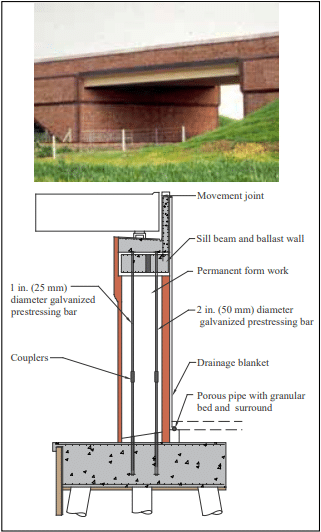
Figure 3 shows a cross-section of a bridge abutment and a photograph of the completed bridge where unreinforced post-tensioned brick diaphragm walls were used. Various bridges also use diaphragm walls for the cantilever wingwalls.

Unreinforced diaphragm walls have not been specifically addressed by name in codes and standards in the United States. Even the definition of a diaphragm wall does not exist. However, Building Code Requirements for Masonry Structures (the MSJC Code) includes design methodologies for unreinforced masonry using allowable stress design and strength design, as well as design criteria for composite assemblies. Therefore, unreinforced diaphragm walls can be designed using the existing standards, despite the fact that there is no specifically stated diaphragm wall criteria.

REINFORCED DIAPHRAGM WALLS

Even though unreinforced masonry is possible in areas of the United States, reinforced masonry is more widely adopted. Most regions require reinforcement for commercial masonry construction based upon the International Building Code (IBC) (ref. 6).

The MSJC provides design methodologies for reinforced masonry using allowable stress methods, post-tensioning, and strength design. These provisions can all be applied to reinforced concrete masonry diaphragm walls.

Design Detailing

Regardless of the design method utilized, there are some detailing criteria that apply equally to all reinforced diaphragm walls. These criteria are outlined below.

a) Spacing of Ribs

The ribs of the reinforced diaphragm wall act as webs for out-of-plane loads and connect the wythes structurally to create a composite section.

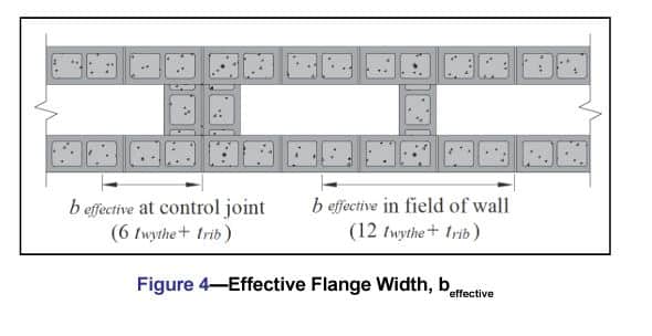
It is preferable that the ribs be spaced so that the flanges are fully effective in resisting applied loads. This is controlled by MSJC Section 5.1.1.2 which governs wall intersections. For reinforced walls where both flanges experience compression and tension, the MSJC requires the effective flange width on either side of the web to not exceed 6 times the flange thickness or 0.75 times the floor-to-floor height. In addition, the effective flange width must not extend past a control joint.

Therefore, the effective clear spacing between ribs is 12·twythe for walls without control joints (6·twythe from each rib), and the effective flange width is 12·twythe plus trib. Figure 4 illustrates how this effective flange width is smaller when a control joint is located at a rib. When placing a control joint between ribs, center the control joint and the effective flange remains 12·twythe plus trib.


b) Flange Thickness

The masonry unit selected for the flange wythe dictates the flange thickness (twythe). To accommodate reinforcement, a 6-in. (152-mm) concrete masonry unit is the smallest practical unit to be used. Larger units can be used to accommodate larger bars and provide larger compression areas.

c) Grouting

The choice of full vs. partial grouting is a function of design:

1. If the compression area required by out-of-plane
design exceeds the face shell thickness of the wythe,
the recommendation is to fully grout the flanges. Alternatively, the designer can use partial grouting and perform a T-beam analysis on the wall.

2. If the compression area does not exceed the face
shell thickness of the wythe, either partial or full
grouting can be used without using the more cumbersome T-beam analysis.

3. The ribs are often fully grouted, but they can also
be designed with partial grouting.

d) Masonry Bond

TMS 402 Section 5.1.1.2.1 requires that intersecting walls be constructed in running bond for composite flanging action to occur. Therefore, reinforced diaphragm walls are always constructed in running bond.

e) Connecting the Ribs to the Wythes

MSJC Section 5.1.1.2.5 requires that the connection of intersecting walls conform to one of the following requirements:

1. At least fifty percent of the masonry units at the interface
must interlock.

2. Walls must be anchored by steel connectors grouted into
the wall and meeting the following requirements:

(a) Minimum size: 1/4 in. x 1-1/2 in. x 28 in. (6.4 x 38.1 x711 mm) including a 2-in. (50.8-mm) long, 90-degree bend at each end to form a U or Z shape.
(b) Maximum spacing: 48 in. (1,219 mm).

3. Intersecting reinforced bond beams must be provided at a maximum spacing of 48 in. (1,219 mm) on center. The minimum area of reinforcement in each bond beam is 0.1 in.2 per ft (211 mm2/m) multiplied by the vertical spacing of the bond beams in feet (meters). Reinforcement is required to be developed on each side of the intersection.

The use of bond beams in requirement 3 above is one
way of handling the interface shear requirement. However,
the equations below can also be used for this purpose:
For allowable stress design:
fv = V/An TMS 402 Section 8.3.5.1.1 (Eqn. 8-21)
where Fv is controlled by Section 8.3.5.1.2.
For strength design, the shear strength, fv, is controlled by
Sections 8.3.5.1.2 and 8.3.5.1.4.

f) Control (Movement) Joints

CMU-TEC-009-23, Crack Control Strategies for Concrete Masonry Construction (ref. 7) are the industry standards for determining control joint spacing. Both were developed for single wythe walls with and without horizontal reinforcement.

There is no specific research on shrinkage characteristics of reinforced diaphragm walls. The expectation is that the ribs restrain shrinkage movement of the wythes and the resulting spacing of control joints can be increased over what would be expected for a single wythe wall. Until research becomes available, however, the current recommendation is to use the existing industry crack control recommendations to space control joints for reinforced diaphragm walls.

Additional attention must be placed on the size of the corner control joints if the diaphragm walls are used to support out-ofplane loads (see Example 1).

Allowable Stress Design of Reinforced Diaphragm Walls

Reinforced masonry designed using allowable stress design (ASD) methods follows similar guidelines as that used for unreinforced masonry. The maximum wall height is controlled by the loadings and slenderness effects. The slenderness effects are based upon the h/r ratio and prevent the wall from buckling.

The design methodology for reinforced diaphragm walls is similar to reinforced single wythe wall design and is discussed in TEK 14-07C, ASD of Concrete Masonry (2012 IBC & 2011 MSJC) (ref. 8).

Strength Design of Reinforced Diaphragm Walls

The strength design method has no specific limit on h/t. However, it has design criteria that limit service load deflections and ultimate moment capacity for out-of-plane loads. The service load deflections cannot exceed 0.7 percent of the wall height. For a 30-ft (9.1 m) wall, that is 2.5 in. over 30 ft (64 mm over 9.1 m) for a simply supported wall.

There is an axial load capacity limitation when h/t exceeds 30: the factored axial load for these walls must be limited to 5 percent of f’m based upon the gross section properties.

The design methodology is similar to single wythe design and is discussed in CMHA TEK 14-11B, Strength Design of CM Walls for Axial Load & Flexure (ref. 9)


Reinforced Concrete Masonry Diaphragm Walls Using Post-tensioned Masonry Design

Post-tensioned masonry design of diaphragm walls is the same as single wythe design. However, the large void in diaphragm walls provides an opportunity for the tendons to be placed eccentrically as needed for the loadings. Placed inside the void, the tendons are generally unbonded and unrestrained.

Seismic Design

The MSJC Code and ASCE 7 (refs. 1, 11) provide additional criteria for seismic design of walls that need to be considered as for any other masonry wall. This includes the degree of grouting and the inclusion of prescriptive reinforcement.

DESIGN EXAMPLE: WINGWALL DESIGN FOR A REINFORCED CONCRETE MASONRY MAINTENANCE STORAGE FACILITY

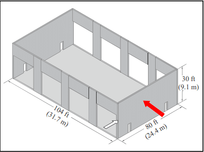
Figure 5 shows the basic building layout for the design example. The front and rear walls are perforated with 20 ft x 20 ft (6.1 x 6.1 m) overhead doors for vehicle access. Control joints are shown over the door openings; the pier sections are 6 ft (1.8 m) in length. The endwalls have personnel access openings. Because the front and rear walls are perforated, the pier sections may not have sufficient in-plane stiffness and strength. Therefore, the endwalls should be designed to brace the building in both directions.

Although the roof structure is not shown, long-span joists bear on the front and rear sidewalls (i.e., the walls with the large perforations); the endwalls are nonloadbearing. The roof diaphragm would be designed to distribute the frontrear lateral loads to the endwalls, which must be designed as conventional shear walls. Conventional shear wall design is covered by the Masonry Designer’s Guide (ref. 12) and is not covered here.

The roof diaphragm will not be used to brace the side-toside lateral forces. For this example, the out-of-plane design (the large red arrow in Figure 5 depicts the out-of-plane load) will treat the endwalls as diaphragm walls acting as cantilevers to brace the building for the side-to-side lateral loads similar to Figure 2. This decision exempts the roof diaphragm from the strength and stiffness requirements for lateral loads that are perpendicular to the plane of the roof trusses. These requirements are typically met by horizontal braces between roof trusses.

Input:
Location: Coastal US, South Carolina
Loadings: ASCE 7-16, Part 2 for wind design
Masonry Standard: TMS 402, ASD method Because no bracing is used at the top of the wall, component and cladding loads will be used to design the wall.

1. Proposed wall section

Use 6-in. (152-mm) concrete masonry units for wythes and 8-in. (203-mm) for ribs (see Figure 1).

Masonry units: ASTM C90 (ref. 12), f’m = 2,000 psi (13.8 MPa); unit weight 125 pcf (2,000 kg/m3)
Reinforcement: ASTM A615 (ref. 13), Grade 60
Grout: ASTM C476 (ref. 14), 2,000 psi (13.8 MPa)
Mortar: ASTM C270 (ref. 15), Type S 

2. Select control joint spacing

The three possible options are:
a) Using CMU-TEC-009-23 (empirical method), space control joints at the lesser of 1.5h = 45 ft (13.7 m), max 25 ft (7.62 m). The 25 ft (7.62 m) criteria governs. The required horizontal reinforcement in the walls is 0.025 in.2/ft (CMUTEC-009-23, Table 1). This corresponds to two-wire W1.7 TEK 14-24 5 CONCRETE MASONRY & HARDSCAPES ASSOCIATION masonryandhardscapes.org (9 gauge, MW11) joint reinforcement at 16 in. (406 mm) on center vertically over the height of the wall (CMUTEC-009-23, Table 2).

b) Using CMU-TEC-009-23 (alternative engineered method), space control joints at the lesser of 2.5h = 75 ft or 25 ft (7.62 m). Again, the 25 ft (7.62 m) criteria governs. The required horizontal reinforcement in the walls is 0.0007An , which corresponds to 0.064 in2/ft or two-wire W1.7 (9 gauge, MW11) wire joint reinforcement at 24 in. (610 mm) on center vertically over the height of the wall (CMUTEC-009-23, Table 5).

c) Using CMU-TEC-009-23, space control joints at any length provided the horizontal reinforcement in the walls exceeds 0.002An (CMU-TEC-009-23). This corresponds to 0.183 in2/ft or two No. 6 (M#19) reinforcing bars in bond beams at 32 in. (813 mm) on center vertically over the height of the wall (CMU-TEC-009-23, Table 6 for fully grouted walls).

To minimize the possible number of control joints, select option c) with the horizontal bond beams. Provide control joints only at the corners (Figure 5). If the designer chooses to use horizontal joint reinforcement and not bond beams, the maximum control joint spacing would be 25 ft (7.62 m) using either options a) or b).

While the inner wythe will generally be exposed principally to shrinkage with only minor thermal effects, it is common to reinforce both wythes similarly.

3. Determine wind loads

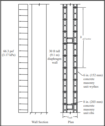
From ASCE 7-16 Part 2, the suction load at the Exterior Zone (5) is calculated as 66.3 psf (3.17 kPa) (see Figure 6). In ASCE 7, wind loads are strength level. Roof dead load is ignored at the nonbearing wall.

4. Determine base of wall loads

Vu = 66.3 psf × 30 = 1,989 lb/ft of wall (29.0 kN/m)
Mu = 66.3 x (30)2/2= 29,835 ft-lb/ft of wall (132 kN-m/m)
Vser = 0.6 Vu = 1,193 lb/ft of wall (17.4 kN/m)
Mser = 0.6 Mu = 17,901 ft-lb/ft of wall (79.6 kN-m/m)
Note: 0.6 reduces Vu to ASD per ASCE 7.

5. Determine beffective

in field of wall (solid region away from openings):
beffective = 12twythe + trib = 12(6 in.) + 8 in. = 80 in. (2,032 mm)

6. Determine minimum twall to satisfy shear capacity

Vrib = Vser × 80/12 = 7,953 lb (35.4 kN)
fv = Vrib/Arib = 7,953/[(7.63 in.)·twall] (TMS 402, Equation 8-21)
Fv ≤ 2 √f’m γg = 89 psi, assuming M/Vd > 1.0 and γg = 1.0 (MSJC Code, Equation 8-24)
This produces twall ≥ 11.7 in. (297 mm)
Checking M/Vd = 17,901/[1,193 x (<1 ft)] = 15.0 > 1.0 OK
Shear is not an issue. The prescriptive requirements for the
intersection of the ribs and flanges are sufficient.

7.Determine minimum twall due to moment capacity

Try a rib length of 1.5 courses of concrete masonry.
twall = 15.625 in. unit + 0.375 in. mortar joint + 7.625 in. half
unit = 23.63 in. (600 mm)
d = 23.63 in. – (5.63 in./2) = 20.82 in. (529 mm)
Ignoring axial load,
As (estimated) = Mser /(2.16d)
= (17,901/1,000)(2.16 x 20.82 in)(529 Mm)
Try No. 8 at 24 in. o.c. (As = 0.40 in.2/ft) (M#25 at 610 mm o.c.)


8. Determine wall dead load at base of wall

From CMU-TEC-002-23 (ref. 16): wall weight of 125 pcf 6 in. fully grouted concrete masonry = 62 psf (303 kg/m2 )

125 pcf 8 in. fully grouted = 84 psf (411 kg/m2 )
Flange load: 2 wythes x 62 psf = 124 psf per ft
Rib load: [23.63 in. – 2(5.63 in.)]/12 x 84 psf/80 in./12 = 13.0 psf/ft of wall

PDL = (124 + 13.0) x 30 ft = 4,110 lb/ft of wall (60 kN/m)

9. Load combination

0.6 PDL + 0.6W from ASCE 7-10 for ASD

Note: This one load combination is shown for this example. The designer must check all combinations required by ASCE 7.
P = 0.6PDL = 0.6 (4,110) = 2,466 lb/ft (36 kN/m)
M = 0.6 Mu, wind = Mser = 17,901 ft-lb/ft (79.6 kN-m/m)

10. Determine n

From MSJC Section 4.2.2:
Es = 29,000,000 psi (200,000 MPa)
Em = 900f’m = 1,800,000 psi (12,410 MPa) n = Es/Em = 16.1
For As = 0. 44 in.2 /ft (from 7 above),

= nAs /bd = 16.1(0.4)/12(20.82) = 0.026
If P = 0,  k = √ (nρ)2 + 2nρ – nρ = 0.204;
j = 1- (k/3) = 0.932

kd = 4.25 > tface of 6-in. CMU but less than the wythe thickness. Axial load may increase kd. Therefore, grouting the full
wythe is appropriate.

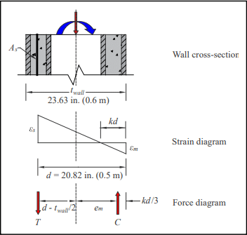
11. Design for PDL and M

(see Figure 7)
From statics: P = CT
M = C x em + T (dtwall/2)
Per foot: C = 1/2(kd)fm x 12 in.
fm = Em εm
T = As fs
fs = Es εs
em = twall/2 – kd/3

From strain compatibility: εm/kd = εs(dkd)
(fm /Em)/kd = (fs/Es)/(dkd) → fs = n [(dkd)/kd] fm
Therefore, C = 6(kd)fm
T = 0.4(16.1)((20.82 – kd)/kd)) fb
= 6.44((20.82 – kd)/(kd)) fb
Solving for P = CT and M = C em + T (dtwall/2)
gives kd = 4.65 in. (118 mm) and fb = 498 psi (3.4 MPa)
Checking:
C = 12,449 lb (55 kN)
T = 10,030 lb (44 kN)
P = 2,419 lb (10.7 kN) OK
em = twall/2 – kd/3 = 10.27 in. (264 mm)
M = C em + T (dtwall/2)
= 12,449(10.27)/12 + 10,030(20.82 – 23.63/2)/12
= 18,185 ft-lb approx. = M =17,901 ft-lb OK
Check:
fm = 498 psi < Fb = 0.45 f’m = 900 psi (6.2 MPa)
OK (TMS 402 8.3.4.2.2)
fs = 16.1((20.82 – 4.86)/4.86) 417 psi = 22,047 psi (152 MPa)
fs < Fs = 32,000 psi (221 MPa) OK (MSJC 8.3.3.1)

MSJC Section 8.3.4.2.2 requires an additional check for fa alone. The design engineer is generally advised to perform this check. However, it rarely controls for diaphragm walls due to the stiff wall section. For this example, there is no applied axial load so the check is not required.

Therefore, this section checks using No. 8 bars at 24 in. on center (M#25 at 610 mm) in a fully grouted diaphragm wall. Note that this only applies to the end zone in suction. The design calculations should be repeated:

a. for pressure load on the end zone,

b. for pressure and suction over the interior zone,

c. over the height of the wall to reduce the amount of vertical reinforcement, and

d. the design should be checked adjacent to control joints and openings.

Using the walls to support of out-of-plane loads requires the foundations to be designed and detailed for the cantilever walls.

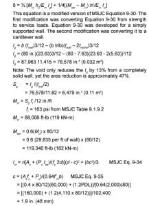
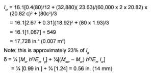
12. Check deflection at top of the wall for a cantilever

Using loads and section properties for beffective.


Provide the control joints between the sidewalls and the front/ rear walls. Construct with sealant that has a shear capacity of 50% of the joint thickness, the joint thickness should exceed 2 x 0.56 in. = 1.12 in. (28 mm). See white arrow on Figure 5.  


SUMMARY

Reinforced concrete masonry diaphragm walls provide opportunities for engineers to design a) very tall walls and b) brace walls using the diaphragm walls as cantilevers. For buildings, these are two unique options that are not normally available from traditional masonry walls.

NOTATIONS

An = net cross-sectional area of a member, in.2 (mm2)
As = area of nonprestressed longitudinal tension reinforcement, in.2(mm2)
b = width of section, in. (mm)
beffective = effective width of section, in. (mm)
C = resultant compressive force, lb (N)
c = distance from the fiber of maximum compressive
strain to the neutral axis, in. (mm)
d = distance from extreme compression fiber to centroid of tension reinforcement, in. (mm)
Em = modulus of elasticity of masonry in compression, psi (MPa)
Es = modulus of elasticity of steel, psi (MPa)
em = eccentricity of axial load, in. (mm)
Fm = allowable compressive stress, psi (MPa)
fm = calculated compressive stress in masonry due to axial and flexure, psi (MPa)
Fv = allowable shear stress, psi (MPa)
Fs = allowable tensile or compressive stress in reinforcement, psi (MPa)
fa = calculated compressive stress in masonry due to axial load only, psi (MPa)
f’m = specified compressive strength of clay masonry or concrete masonry, psi (MPa)
fr = modulus of rupture, psi (MPa)
fs = calculated tensile or compressive stress in reinforcement, psi (MPa)
fv = calculated shear stress in masonry, psi (MPa)
fy = specified yield strength of steel for reinforcement and anchors, psi (MPa)
h = effective height of wall, in. (mm)
Icr = moment of inertia of cracked cross-sectional area of a member, in 4 (mm4)
Ig = moment of inertia of gross cross-sectional area of a member,, in.4 (mm4)
j = ratio of distance between centroid of flexural compressive forces and centroid of tensile forces to
depth, d
k = ratio of the distance between the compression face of an element and the neutral axis to the effective depth d
M = maximum moment at the section under consideration, in.-lb (N-mm)
Mcr = nominal cracking moment strength, in.-lb (N-mm)
Mser = service moment at midheight of a member, in.-lb (N-mm)
Mu = factored moment, magnified by second-order effects where required by the code, in.-lb (N-mm)
n = modular ratio, Es/Em
P = axial load, lb (N)
PDL = axial load due to dead load, lb (N)
Pu = factored axial load, lb (N)
r = radius of gyration, in. (mm)
Sg = section modulus of the gross cross-sectional area
of a member, in.3(mm3)
T = resultant tensile force, lb (N)
t = nominal thickness of member, in. (mm)
tface = specified thickness of masonry unit faceshell, in. (mm)
trib = specified thickness of diaphragm wall rib, in. (mm)
tsp = specified thickness of member, in. (mm)
twall = specified thickness of wall, in. (mm)
twythe = specified thickness of the masonry wythe, in. (mm)
V = shear force, lb (N)
Vrib = shear capacity (resisting shear) of diaphragm wall rib, lb (N)
Vser = service level shear force, lb (N)
Vu = factored shear force, lb (N)
W = wind load, psf (kPa)
γg = grouted shear wall factor
δ = moment magnification factor
εm = compressive strain of masonry
εs = strain of steel
f = strength reduction factor
ρ = reinforcement ratio

References

  1. Building Code Requirements for Masonry Structures, TMS 402-16, Reported by The Masonry Society 2016.
  2. Construction of Reinforced Concrete Masonry Diaphragm Walls, TEK 03-15, Concrete Masonry & Hardscapes Association, 2017.
  3. Aggregate Concrete Blocks: Unreinforced Masonry Diaphragm Walls, Data Sheet 10. Concrete Block Association of Great
    Britain, March 2003.
  4. Flashing Details for Concrete Masonry Walls, TEK 19-05A, Concrete Masonry & Hardscapes Association, 2008.
  5. Design for Dry Single-Wythe Concrete Masonry Walls, TEK 19-02B, Concrete Masonry & Hardscapes Association, 2012.
  6. International Building Code. International Code Council, 2015/2018.
  7. Crack Control Strategies for Concrete Masonry Construction, CMU-TEC-009-23, Concrete Masonry & Hardscapes Association, 2023.
  8. TEK 14-07C, ASD of Concrete Masonry (2012 IBC & 2011 MSJC). Concrete Masonry & Hardscapes Association, 2013.
  9. TEK 14-11B, Strength Design of CM Walls for Axial Load & Flexure. Concrete Masonry & Hardscapes Association, 2003.
  10. Minimum Design Loads for Buildings and Other Structures, ASCE/SEI 7-10. American Society of Civil Engineers, 2010.
  11. Masonry Designers’ Guide, Seventh Edition, MDG-7. The Masonry Society, 2013.
  12. Standard Specification for Loadbearing Concrete Masonry Units, ASTM C90-14. ASTM International, Inc., 2014.
  13. Standard Specification for Deformed and Plain CarbonSteel Bars for Concrete Reinforcement, ASTM A615/ A615M-14. ASTM International, Inc., 2014.
  14. Standard Specification for Grout for Masonry, ASTM C476-10. ASTM International, Inc., 2010.
  15. Standard Specification for Mortar for Unit Masonry ASTM C270-14. ASTM International, Inc., 2014.
  16. Weights and Section Properties of Concrete Masonry Assemblies, CMU-TEC-002-23.Concrete Masonry & Hardscapes Association, 2023.

Structural Design of Unreinforced Composite Masonry

INTRODUCTION

Concrete masonry offers many textures, colors and sizes, along with choices in bond patterns and joint treatment making it an excellent choice for exterior and interior walls in residential, commercial and public buildings. Concrete brick can be used in both structural and veneer applications and is economical, durable, easy to maintain, fire resistant, and reduces sound transmission.

Multi-wythe masonry walls are classified as either composite or noncomposite depending on how the wythes interact. Connections between wythes of composite walls are designed to transfer stresses between the wythes, allowing the wythes to act as a single member in resisting loads. In contrast, for noncomposite or cavity walls each wythe individually resists the loads imposed on it. Concrete brick are used both in composite walls and as nonloadbearing veneer in cavity wall construction. Requirements for concrete brick veneers are summarized in Concrete Masonry Veneers, TEK 03-06C (ref. 1).

Standard Specification for Concrete Building Brick, ASTM C 55 (ref. 2), governs concrete brick and similar solid units. C 55 requirements are summarized in Concrete Masonry Unit Shapes, Sizes, Properties, and Specifications, CMUTEC-001-23 (ref. 3). 


STRUCTURAL DESIGN METHODS

Composite wall structural design requirements are contained in Building Code Requirements for Masonry Structures (ref. 4) and the International Building Code (ref. 5).

Allowable stress design of unreinforced composite walls is typically governed by the flexural tensile capacity of the masonry system (see Table 1), although compression and shear must also be checked. Shear stress in the plane of interface between wythes and collar joints is limited to 5 psi (34.5 kPa) for mortared collar joints; 10 psi (68.9 kPa) for grouted collar joints; and the square root of the unit compressive strength of the header (over the net area of the header) for headers.

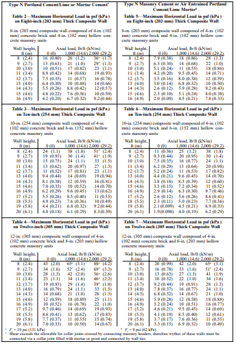
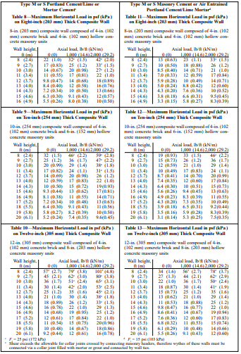
Tables 2 through 13, for lateral loads with or without concentric axial loads (see Figure 1), are based on Chapter 2, Allowable Stress Design, of Building Code Requirements for Masonry Structures (ref. 4) and the following:

  1. specified compressive strength of masonry, f’m = 1500 psi (10.3 MPa),
  2. section modulus based on the minimum net area of the composite wall cross section,
  3. faceshell and web dimensions based on ASTM C 90 (ref. 6) minimum requirements for hollow units,
  4. loads include increase in allowable stress for load combinations including wind or seismic (where increase does not apply, multiply the Table values by ¾), and
  5. allowable tensile stress in masonry, Ft, for hollow ungrouted concrete masonry normal to the bed joints is as noted in Table footnotes.

CONSTRUCTION

Concrete brick walls and wythes of concrete brick should be laid with full head and bed mortar joints. For composite construction, the collar joint (the vertical longitudinal joint between wythes of masonry) is filled with grout or mortar to allow structural interaction between the wythes.

In composite walls, Building Code Requirements for Masonry Structures (ref. 4) requires that concrete brick be bonded to the backup wythe using either masonry headers or wall tie and grout or mortar. These minimum requirements, described below, help ensure that composite action is present between the wythes.

When bonded using masonry headers, the headers must make up at least 4 percent of the wall surface and extend at least 3 in. (76 mm) into the backing. The shear stress developed in the masonry header is limited to the square root of the unit compressive strength of the header (in psi (MPa) over the net area of the header).

Figure 2 illustrates wall tie spacing requirements for composite walls bonded with corrosion resistant ties or wire and collar joints filled with mortar or grout. Cross wires of joint reinforcement and rectangular ties are commonly used as wall ties for composite walls. Z-ties, however, are not permitted with ungrouted hollow masonry (ref. 7).

For cavity wall construction, the following construction recommendations apply:

  • keep cavity substantially clean to allow free water drainage,
  • install weep holes at 32 in. (813 mm) o. c.,
  • install granular fill, mesh or other mortar collection device in bottom of cavity to prevent mortar droppings from blocking weep holes, and
  • embed wall ties at least 1 ½ in. (38 mm) into the mortar bed of solid units.

REFERENCES

  1. Concrete Masonry Veneers, TEK 03-06C, Concrete Masonry & Hardscapes Association, 2012.
  2. Standard Specification for Concrete Brick, ASTM C 55-01. American Society for Testing and Materials, 2001.
  3. Concrete Masonry Unit Shapes, Sizes, Properties, and Specifications, CMU-TEC-001-23, Concrete Masonry & Hardscapes Association, 2023.
  4. Building Code Requirements for Masonry Structures, ACI 530-99/ASCE 5-99/TMS 402-99. Reported by the Masonry Standards Joint Committee, 1999.
  5. International Building Code. International Code Council, 2000.
  6. Standard Specification for Loadbearing Concrete Masonry Units, ASTM C 90-01. American Society for Testing and Materials, 2001.
  7. Specification for Masonry Structures, ACI 530.1-99/ ASCE 6-99/TMS 602-99. Reported by the Masonry Standards Joint Committee, 1999.

Foam Plastic Insulation in Concrete Masonry Walls

INTRODUCTION

Foam plastic insulation is often used in exterior concrete masonry construction to improve steady state thermal performance (R-values), and in some cases to improve air and moisture infiltration properties as well. Because of their potential flammability and smoke generation in case of fire, the International Building Code (IBC) (ref. 1) imposes additional requirements on these materials when they are used in exterior walls. These requirements are covered in IBC section 2603.

Foam plastic insulations include both rigid board (expanded polystyrene, extruded polystyrene, polyisocyanurate) as well as open cell and closed-cell spray-applied or foamed-in-place insulations. They may be used on the interior, exterior or in the cores (as either inserts or foamed-in-place) of single wythe masonry walls, and in the cavities of masonry cavity walls.

Because these plastics are flammable, the IBC mandates that they be protected by fire-resistance-rated materials or assemblies in wall and roof assemblies, to prevent the plastic insulation from contributing to the spread of fire in a building.

This TEK describes the IBC requirements for assemblies containing foam plastic insulation and presents details of concrete masonry walls that comply with those requirements. Note that this TEK focuses on the requirements for masonry wall assemblies: there may be additional requirements for the insulation, such as flame spread index and labeling.

IBC REQUIREMENTS

IBC Section 2603 regulates the use of foam plastic insulation in all types of construction, both combustible and noncombustible, with the intent of limiting the spread of fire via these materials. For exterior walls, Section 2603 requires:

  • a thermal barrier between foam plastic insulation and the building interior, which can be satisfied with a 1 in. (25 mm) minimum thickness of concrete or masonry,
  • ignition testing for foam plastic insulations applied to wall exteriors, although assemblies protected with at least 1 in. (25 mm) of concrete or masonry on the exterior are exempt from testing, and
  • successful testing in accordance with NFPA 285, Standard Fire Test Method for Evaluation of Fire Propagation Characteristics of Exterior Non-Load-Bearing Wall Assemblies Containing Combustible Components (ref. 2).

Note that there are two important exceptions to the requirement for NFPA 285 testing:

  1. Wall assemblies where the foam plastic insulation is covered on each face by a minimum 1 in. (25 mm) thickness of masonry or concrete and meeting one of the following:
    a) there is no air space between the insulation and the concrete or masonry (as occurs with foamed-in-place insulation); or
    b) the insulation has a flame spread index of 25 or less as determined by ASTM E84, Standard Test Method for Surface Burning Characteristics of Building Materials, or UL 723, Standard for Test for Surface Burning Characteristics of Building Materials, (refs. 3, 4) and the air space between the insulation and the concrete or masonry does not exceed 1 in. (25 mm).
  2. One-story buildings meeting the following conditions: foam plastic with a flame spread index of 25 or less and a smoke-developed index of 450 max can be placed in exterior walls without a thermal barrier where it is covered with aluminum (at least 0.032 in. (0.813 mm) thick) or corrosion-resistant steel (at least 0.0160 in. (0.406 mm) thick), provided that the insulation is not thicker than 4 in. (102 mm), and that the building is equipped with an automatic sprinkler system.

Wall assemblies meeting the requirements listed under number 1 above and buildings meeting the requirements listed under number 2 are deemed to comply with the Section 2603 requirements. Note that in cases where there is less than 1 in. (25 mm) of masonry over the insulation, there are insulations available that will meet the NFPA 285 requirements.

NFPA 285 REQUIREMENTS

NFPA 285 addresses the possibility of fire entering wall cavities through door or window openings, igniting foam plastic insulation and spreading vertically to upper stories.

The test evaluates exterior wall assemblies for buildings required to have exterior walls of noncombustible construction. The test provides a method of determining the flammability characteristics of exterior nonloadbearing wall assemblies. It is intended to evaluate combustible components included within wall assemblies required to be noncombustible, under conditions of a fire originating in the building interior.

NFPA 285 evaluates four conditions:

  • flame propagation over the exterior face;
  • flame propagation within combustible components from one story to the next;
  • vertical flame propagation on the interior wall surface from one story to the next; and
  • lateral flame propagation from one compartment to the next.

To evaluate these conditions, a two-story wall assembly with a window opening on the first floor is constructed in the test assembly. After a 30-minute fire exposure with the burner in the window opening, recorded temperatures are compared to the Standard’s conditions of acceptance to determine compliance. Note that the test evaluates wall assemblies, not specific materials.

SINGLE WYTHE CONCRETE MASONRY WALLS

Single wythe walls may incorporate foam insulation in the cores of the masonry units as either rigid foam inserts or foamed in-place insulation. As discussed above, IBC Chapter 26 essentially requires a minimum of 1 in. (25 mm) of concrete or masonry on the interior and exterior of the foam insulation, as well as protection at headers to prevent ignition of the insulation above door and window openings.

When placed in concrete masonry cores, the foam plastic insulation is protected on the interior and exterior by the concrete face shells. Minimum face shell thickness for concrete masonry units is governed by ASTM C90, Standard Specification for Loadbearing Concrete Masonry Units, (ref. 5) as listed in Table 1. Table 1 shows that concrete masonry units of 6-in. (152 mm) thickness or greater provide the IBC-required 1 in. (25 mm) interior and exterior protection. Because of the small core size of 4-in. (102-mm) units, the cores of these units are rarely insulated. When insulation is placed in the cells of concrete masonry units and bond beams are provided at each story and lintels over each opening, the insulation is fully encapsulated. This meets the intent of the code to prevent the propagation of fire within wall cavities and no further isolation is necessary in this case.

In single wythe construction, door and window headers are typically constructed using either a reinforced precast lintel or a reinforced concrete masonry lintel (shown in Figure 1). This detail provides concrete cover well over the 1 in. (25 mm) minimum required by Section 2603. The detail and level of protection would be similar with a precast concrete lintel. Refer to TEK 19-02B, Design for Dry Single Wythe Concrete Masonry Walls (ref. 6), for additional details on flashing single wythe walls.

MULTI-WYTHE WALLS

Multi-wythe concrete masonry construction is most commonly masonry cavity walls, which often incorporate foam plastic insulation in the cavity formed by the two masonry wythes. In this case, there is more than 1 in. (25 mm) of masonry on both the interior and exterior, so the focus for protecting the insulation is on the headers and jambs of window and door openings.

Per Building Code Requirements for Masonry Structures (ref. 8) concrete masonry veneer walls are to have a minimum specified 1 in. (25 mm) air space with special precautions to limit mortar overhangs inside the cavity to allow adequate drainage between the wythes. Exception b to NFPA 285 testing (see page 1) limits the air space between the insulation and the masonry to 1 in. (25 mm) maximum. Therefore, when exception b is being used, the designer should specify a 1 in. (25 mm) air space to meet both requirements.

Figure 3 shows a window top of opening detail in a concrete masonry cavity wall. In this case, 1 in. (25 mm) of mortar is slushed into the cavity below the insulation to provide the required level of protection. In addition, testing (refs. 7, 10) has shown that mineral wool fire safing covering insulation board exposed at openings in a masonry cavity wall is sufficient to pass NFPA 285 requirements. Note that mineral wool insulation cannot be exposed to the moisture in the drainage cavity. If used, it must be behind flashing or similarly protected.

The jambs of metal doors (see Figure 4) are typically filled with mortar as the wall is constructed, again providing adequate protection for the insulation.

For wood door jambs, several options are shown in Figures 5 and 6. Figure 5 shows a detail where the insulation is held 1 in. (25 mm) back from the jamb. An additional piece of insulation bridges the cavity and acts as a backer for a 1 in (25 mm) layer of mortar. Another option is shown in Figure 6, where the unit adjacent to the jamb is turned 90o, and the unit is cut so that part of the face shell extends across the cavity, between the jamb and the insulation. On the alternate courses, a piece of the cut face shell can be mortared across the cavity to provide the protection. Wood window jamb details are very similar, as shown in Figures 7 and 8.

REFERENCES

  1. International Building Code. International Code Council, 2015.
  2. Standard Fire Test Method for Evaluation of Fire Propagation Characteristics of Exterior Non-Load-Bearing Wall Assemblies Containing Combustible Components, NFPA 285. National Fire Protection Association, 2012.
  3. Standard Test Method for Surface Burning Characteristics of Building Materials, ASTM E84-13a. ASTM International, 2013.
  4. Standard for Test for Surface Burning Characteristics of Building Materials, UL 723. Underwriter’s Laboratories, 2008.
  5. Standard Specification for Loadbearing Concrete Masonry Units, ASTM C90-13. ASTM International, 2013.
  6. Design for Dry Single-Wythe Concrete Masonry Walls, TEK 19 02B. Concrete Masonry & Hardscapes Association, 2012.
  7. NFPA 285-[06] Approved Wall Assemblies Using Foam Plastic Insulation From Dow, Tech Solutions 514.0. Dow Chemical Company, 2009.
  8. Building Code Requirements for Masonry Structures, TMS 402 11/ACI 530-11/ASCE 5-11. Reported by the Masonry Standards Joint Committee, 2011.
  9. Standard Test Method for Determining Ignitability of Exterior Wall Assemblies Using a Radiant Heat Energy Source, NFPA 268. National Fire Protection Association, 2012.
  10. Commercial Complete™ Wall System NFPA 285 Tested Wall Assemblies. Owens Corning Insulating Systems, LLC, 2012.

Concrete Masonry in the 2012 Edition of the IECC

INTRODUCTION

Although masonry is an ancient material, today’s concrete masonry can be a significant benefit to modern sustainable buildings. In addition to its energy efficiency, concrete masonry is a locally produced natural material that is durable and long lived, minimizing the need for repair or replacement. Concrete masonry can incorporate recycled materials, and can itself be reused or recycled at the end of its life. Various architectural finishes are available that can eliminate the need for paint or other coatings which can impair indoor air quality or impede moisture control.

The International Energy Conservation Code (IECC) (ref. 1) serves as a written model for states, counties, cities or other jurisdictions to develop local codes for energy efficient building design. Concrete masonry construction can help meet these energy requirements, while also providing superior structural capacity, durability, and resistance to fire, sound transmission, insects and mold.

This TEK describes concrete masonry wall compliance for commercial buildings in accordance with the 2012 edition of the IECC.

CONCRETE MASONRY ENERGY PERFORMANCE

The thermal performance of a masonry wall depends on its steady state thermal characteristics (described by R-value and U-factor) as well as its thermal mass (described by heat capacity).

The steady-state and thermal mass performance are influenced by the size and type of masonry unit, cross-web configuration, type and location of insulation, finish materials, and density of masonry. Concrete masonry units (CMU) made with lower density concrete have higher R-values (i.e., lower U-factors) than units made with higher density concrete.

Thermal mass is the ability of materials such as concrete masonry to store heat—they heat up and cool down slowly, which can help mitigate heating and cooling loads. Due to the significant benefits of concrete masonry’s inherent thermal mass, concrete masonry buildings can often provide similar thermal performance to more heavily insulated frame buildings. The benefits of thermal mass have been incorporated into energy code requirements and computer models. The IECC and ANSI/ASHRAE/IESNA Standard 90.1, Energy Standard for Buildings Except Low-Rise Residential Buildings (ref. 2), permit concrete masonry walls to have less insulation than frame wall systems and metal buildings to meet the energy requirements

COMPLIANCE OPTIONS

For commercial buildings, there are three alternatives for demonstrating building energy compliance:

  1. Prescriptive compliance, which requires each building envelope element to independently meet the R-value or U-factor requirements listed in IECC Table C402.1.2 or Table C402.2(1). The approach is simple to implement, but offers no design flexibility.
  2. A building envelope trade-off procedure, which demonstrates that the envelope as a whole meets the energy requirements. This approach allows more design flexibility, since elements that do not meet prescriptive IECC requirements can be offset by other elements with higher performance. Although not specifically referenced in the code, COMcheck software (ref. 3) developed by the U. S. Department of Energy is a commonly accepted compliance tool for demonstrating total envelope performance.
  3. A total building performance analysis, which simulates a full year of building operation. The analysis treats the entire building as a system, and accounts for virtually all aspects of building energy use, including the building envelope, mechanical systems, service water heating, and electric power and lighting. Detailed energy simulation software, such as EnergyPlus or eQuest (refs. 4, 5), is typically used when employing this option. This compliance path offers the maximum design flexibility, but requires a fairly rigorous and detailed analysis. For a project which will be LEED certified, a total building analysis is required, and the prescriptive criteria need not be met. See TEK 06-09C, Concrete Masonry and Hardscape Products in LEED 2009, (ref. 6) for more detailed information.

Note that a project need only comply under one of these compliance options, not all three. The following sections briefly describe prescriptive and trade-off compliance. See the design example at the end of the TEK for how these options may be implemented.

IECC PRESCRIPTIVE COMPLIANCE

Of the three compliance methods, the prescriptive method is easiest to apply. Requirements for building envelope components are listed in table format, by climate zone. Figure 1 illustrates the IECC climate zones.

Under the prescriptive option, requirements for individual elements are independent of each other. Hence, although using the prescriptive tables is very straightforward, it can also be very limiting in terms of design flexibility.

The IECC prescriptive building envelope requirements for commercial buildings (IECC section 402) list minimum energy performance criteria for roofs, above and below grade walls, slab-on-grade floors, and fenestration. The wall, roof and floor requirements are stated in terms of maximum assembly U-factor or minimum insulation R-value. The user may choose to use whichever table is more applicable to the project’s assemblies.

In the IECC prescriptive tables, concrete masonry walls fall under the Mass Wall category, which is defined as walls weighing at least 35 psf (171 kg/m2), or 25 psf (122 kg/m2) if the material weight is not more than 120 lb/ft3 (1,900 kg/m3).

Prescriptive Compliance via Overall Wall U-Factor

The 2012 IECC prescriptive U-factor requirements for above and below grade walls are shown in Table 1. U-factor is numerically the inverse of R-value. So, a wall with an overall R-value of 10 h. ft2.oF/Btu (1.76 m2.oK/W) has a U-factor of 0.10 Btu/h. ft2.oF (0.568 W/m2.oK) and vice-versa.

Using the U-factor criteria, rather than the insulation R-values discussed below, allows walls without continuous insulation (such as concrete masonry with insulated cores) to comply prescriptively. The U-factor compliance table may also be a good option for concrete masonry walls with proprietary inserts, or other walls that have better thermal performance than that assumed in the code.

CMHA TEK 06-02B, R-Values and U-Factors of Single Wythe Concrete Masonry Walls, and TEK 06-01C, R-Values of Multi-Wythe Concrete Masonry Walls, as well as the Thermal Catalog of Concrete Masonry Assemblies (refs. 7, 8, 9) list R-values, and in some cases U-factors, for a wide variety of concrete masonry walls.

Prescriptive Compliance via Insulation R-Value

Table 2 shows minimum insulation R-value requirements for above grade walls. These R-values apply to the insulation only, regardless of the underlying wall’s R-value.

In the table “ci” means continuous insulation. There is a widespread misconception that all walls must have continuous insulation in order to meet the IECC. In fact, continuous insulation is required only to comply with this particular table – other compliance options are available, including compliance via the prescriptive U-factor table discussed above, and COMcheck, discussed below.

Note that in Climate Zones 1 and 2, the IECC includes an exception for single wythe concrete masonry walls with insulated cores. Where the table requires R5.7 continuous insulation, the IECC allows concrete masonry walls with ungrouted cells filled with insulation such as vermiculite, perlite or foamed-in-place (with a thermal conductivity less than or equal to 0.44 Btu-in./h. ft2.oF, or R-value per inch > 2.27 (63.4 W.mm/m2.oK)) to comply, as long as the amount of grouting does not exceed 32 in. (813 mm) o.c. vertically and 48 in. (1,219 mm) o.c. horizontally. The exception allows the majority of single wythe ungrouted and partially grouted concrete masonry walls containing insulation in the ungrouted cells to comply with the IECC, regardless of that wall’s R-value.

TRADE-OFF COMPLIANCE USING COMCHECK

The trade-off option allows the user to demonstrate compliance based on the building envelope as a whole, rather than on the prescriptive component-by-component basis. These trade-offs are most often implemented using easy-to-use software, such as COMcheck (ref. 3).

There are two main benefits to using trade-off software for compliance rather than prescriptive tables. First, the user gains design flexibility because parameters such as increased glazing area can be offset by increasing roof or wall insulation. Second, once the basic building data is entered into the program and saved, design changes or building location can be quickly modified, and compliance immediately redetermined.

More detailed information on using COMcheck for concrete masonry buildings can be found in TEK 06-04B, Energy Code Compliance Using COMcheck (ref. 10).

DESIGN EXAMPLE

Consider a “big-box” retail building in St. Louis, MO (Climate Zone 4). For aesthetics and durability, the designer opts for single wythe core insulated 12-in. (305-mm) concrete masonry walls with an overall wall R-value of 6.3 Btu/h. ft2.oF (1.11m2.oK/W).

The first step is to check if the walls comply using one of the prescriptive compliance options, since they are the easiest to implement. Table 1 shows an above grade mass wall requirement of U0.104 h.ft2.oF/Btu (0.59 W/ m2.oK), which corresponds to a wall R-value of 9.6 Btu/h.ft2.oF (1.69 m2.oK/W). The R6.3 wall does not meet this requirement, nor can Table 2 be used because core insulation does not qualify as continuous insulation.

Using COMcheck, however the building can easily comply, by using the prescriptive minimum level of roof insulation (R25). Note that at the time of publication, because COMcheck did not yet include compliance via the 2012 IECC, compliance was demonstrated using ASHRAE 90.1-2010, which the IECC accepts as an alternate. See TEK 06-04B for more information on compliance using COMcheck.

BUILDING ENVELOPE AIR LEAKAGE REQUIREMENTS

The 2012 IECC includes substantially new air leakage criteria, requiring a continuous air barrier throughout the building envelope. The code also includes several “deemed-to-comply” materials and assemblies which are considered to comply with the code, including fully grouted concrete masonry, various surface coatings, and certain board insulations when installed with taped or sealed joints. The criteria, as well as a full discussion of how the criteria apply to concrete masonry assemblies can be found in TEK 06-14A, Control of Air Leakage in Concrete Masonry Walls, (ref. 11) Figures 2 and 3 in particular.

Concrete Masonry Veneer Details

INTRODUCTION

A wall constructed with two or more wythes of masonry can technically be classified in one of three ways, depending on how each individual wythe is designed and detailed. These three wall systems are composite, noncomposite or veneer walls. A true veneer is nonstructural—any contribution of the veneer to the wall’s out-of plane load resistance is neglected.

Building Code Requirements for Masonry Structures (ref. 1) defines veneer as a masonry wythe which provides the exterior finish of a wall system and transfers out-of-plane loads directly to the backing, but is not considered to add load resisting capacity to the wall system.

Noncomposite walls, on the other hand, are designed such that each wythe individually resists the loads imposed on it. Bending moments (flexure) due to wind or gravity loads are distributed to each wythe in proportion to its relative stiffness.

Composite walls are designed so that the wythes act together as a single member to resist structural loads. This requires that the two masonry wythes be connected by masonry headers or by a mortar or grout filled collar joint and wall ties to help ensure adequate load transfer between the two wythes.

The primary function of anchored veneers is to provide an architectural facade and to prevent water penetration into the building. As such, the structural properties of veneers are neglected in veneer design. The veneer is assumed to transfer out-of-plane loads through the anchors to the backup system. Building Code Requirements for Masonry Structures Chapter 6 (ref. 1) includes requirements for design and detailing anchored masonry veneer.

A masonry veneer with masonry backup and an air space between the masonry wythes is commonly referred to as a cavity wall. The continuous air space, or cavity, provides the wall with excellent resistance to moisture penetration and wind driven rain as well as a convenient location for insulation. This TEK addresses concrete masonry veneer with concrete masonry backup.

DESIGN CONSIDERATIONS

Masonry veneers are typically composed of architectural units such as: concrete or clay facing brick; split, fluted, glazed, ground face or scored block; or stone veneer. Most commonly, anchored masonry veneers have a nominal thickness of 4 in. (102 mm), although 3 in. (76 mm) veneer units may be available as well.

Although structural requirements for veneers are minimal, the following design considerations should be accounted for: crack control in the veneer, including deflection of the backup and any horizontal supports; adequate anchor strength to transfer applied loads; differential movement between the veneer and backup; and water penetration resistance.

The continuous airspace behind the veneer, along with flashing and weeps, must be detailed to collect any moisture that may penetrate the veneer and direct it to the outside. A minimum 1 in. (25 mm) air space between wythes is required (ref. 1), and is considered appropriate if special precautions are taken to keep the air space clean (such as by beveling the mortar bed away from the cavity or by placing a board in the cavity to catch and remove mortar droppings and fins while they are still plastic). Otherwise, a 2 in. (51 mm) air space is preferred. As an alternative, proprietary insulating drainage products can be used.

Although veneer crack control measures are similar to those for other concrete masonry wall constructions, specific crack control recommendations have been developed for concrete masonry veneers. These include: locating control joints to achieve a maximum panel length to height ratio of 11/2 and a maximum spacing of 20 ft (6,100 mm), as well as where stress concentrations occur; incorporating joint reinforcement at 16 in. (406 mm) on center; and using Type N mortar for maximum flexibility. See CMU-TEC-009-23, Crack Control Strategies for Concrete Masonry Construction (ref. 2) for more detailed information.

Because the two wythes in a veneer wall are designed to be relatively independent, crack control measures should be employed as required for each wythe. It is generally not necessary for the vertical movement joints in the veneer wythe to exactly align with those in the backup wythe, provided that the ties allow differential in-plane lateral movement.

Wall ties may be joint reinforcement or wire wall ties. Wall ties for veneers transfer lateral loads to the structural wythe and also allow differential inplane movement between wythes. This second feature is particularly important when the two wythes are of materials with different thermal and moisture expansion characteristics (such as concrete masonry and clay brick), or in an insulated cavity wall which tends to have differential thermal movement between the wythes. When horizontal joint reinforcement is used to tie the two wythes together, hot-dipped ladder type reinforcement is preferred over truss type, because the ladder shape accommodates differential in-plane movement and facilitates placing vertical reinforcement, grout and loose fill insulation. Because veneers rely on the backup for support, wall ties must be placed within 12 in. (305 mm) of control joints and wall openings to ensure the free ends of the veneer are adequately supported. More information on ties for veneers can be found in TEK 03-06C, Concrete Masonry Veneers (ref. 4).

The distance between the inside face of the veneer and the outside face of the masonry backup must be a minimum of 1 in. (25 mm) and a maximum of 4 1/2 in. (114 mm). For glazed masonry veneer, because of their impermeable nature, a 2 in. (51 mm) wide airspace is recommended with air vents at the top and bottom of the wall to enhance drainage and help equalize air pressure between the cavity and the exterior of the wall. Vents can also be installed at the top of other masonry veneer walls to provide natural convective air flow within the cavity to facilitate drying. For vented cavities, it is prudent to create baffles in the cavity at the building corners to isolate the cavities from each other. This helps prevent suction being formed in the leeward cavities.

REFERENCES

  1. Building Code Requirements for Masonry Structures, ACI
    530-02/ASCE 5-02/TMS 402-02. Reported by the Masonry
    Standards Joint Committee, 2002.
  2. CMU-TEC-009-23, Crack Control Strategies for Concrete
    Masonry Construction, Concrete Masonry and Hardscapes
    Association, 2023.
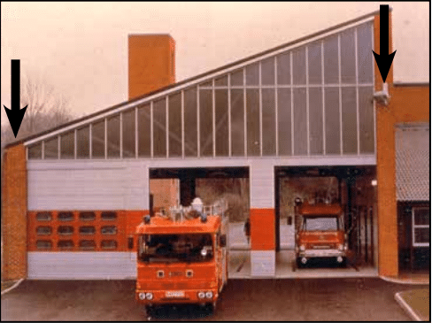
  3. TEK 03-06C, Concrete Masonry Veneers, Concrete
    Masonry and Hardscapes Association, 2012.

Construction of Low-Rise Concrete Masonry Buildings

INTRODUCTION

The current trend of urban renewal and infill has sparked a high volume of new low-rise masonry residences. These structures come in many forms, but quite often they employ the use of load-bearing concrete masonry walls supporting a wood floor system. These new buildings are largely derivative of the historic load bearing masonry “brownstone” or “three flat” structures of old. This guide is intended to assist contractors and architects to give this building type a modern approach to detailing.

FLOOR SYSTEM CONNECTIONS

When designing low-rise loadbearing structures, the connection detail between the floor system and the wall system is critical for achieving a watertight structure. Much of this TEK will deal with which strategy should be utilized in connecting a wood floor system to a masonry load-bearing wall. Connection methods covered are joist hangers, beam pockets and ledger beam details. Other floor systems are used in low-rise construction that are not addressed here – see 05-07A for further information (ref. 2).

BRICK AND BLOCK COMPOSITE WALL DETAILS

Quite often, the front facade of these structures is composed of brick to give the building a more residential, more human scale. One way to construct a brick and block wall is to separate the two wythes with an airspace, creating a cavity wall. Another is to use a composite wall design. The composite wall consists of an exterior wythe of brick directly mortared or grouted and tied to an inner wythe of CMU. The collar joint between the two wythes should be 100% solid as it is the only defense against water penetration. Minimum tie requirements are one tie per 22/3ft2 of wall area for W1.7 (MW11)(9 gauge) wire or one tie per 41/2ft2 of wall area using W2.8 (MW19)(3/16 in.)wire (ref. 2). A W1.7 (MW11)(9 gauge) joint reinforcement @16 in. (406 mm) on center would meet this requirement and is often used. Details covered for this system are base flashing, window head and window sill details.

EXTERIOR CONCRETE MASONRY

The use of water repellent admixtures in concrete masonry and mortars can greatly reduce the amount of water entering the masonry. In addition, they inhibit any water that penetrates the face from wicking to the back of the wall.

Proper selection and application of integral water repellents and surface treatments can greatly enhance the water resistive properties of masonry, but they should not be considered as substitutes for good fundamental design including flashing details and crack control measures. See TEKs 19-01, 19-02A, and 19-04A (refs. 6, 3, & 5) for more information on water resistant concrete masonry construction.

Because a 4 in. (102 mm) concrete masonry veneer will shrink over time, a 4 in. (102 mm) hot-dipped galvanized ladder type joint reinforcement should be placed in bed joints spaced 16 in. (406 mm) vertically.

Compared to type N or O, type S mortar tends to be less workable in the field and should only be specified when dictated by structural requirements. Sills, copings and chimney caps of solid masonry units, reinforced concrete, stone, or corrosion resistant metal should be used. Copings, sills and chimney caps should project beyond the face of the wall at least 1 in. (25 mm) and should have functional flashing and weep holes.

In addition, all sills, copings and chimney caps should have a minimum slope of 1:4, be mechanically anchored to the wall, and should have properly sized, sealed, and located movement joints when necessary.

Flashing should be installed at locations shown on the plans and in strict accordance with the details and industry standard flashing procedures. Functional, unpunctured flashing and weep holes are to be used at the base of wall above grade, above openings, at shelf angles, lintels, wall-roofing intersections, chimneys, bay windows, and below sills and copings. The flashing should be extended past the face of the wall. The flashing should have end dams at discontinuous ends, and properly sealed splices at laps.

JOIST HANGER DETAILS

The use of a joist hanger system can greatly simplify the bearing detail. The floor system does not interrupt the continuity of the bearing wall. Installation is quicker and easier resulting in a more economical installation.

BEAM POCKET DETAILS

The traditional beam pocket detail still can be effective. Stepped flashing above the bearing line is critical to the performance of this system. Without the flashing, any water present in the wall has an unobstructed path inside the building and has the potential to deteriorate the floor structure.

LEDGER BEAM DETAILS

The use of a ledger beam which is bolted to a bond beam is also a good option for this bearing condition. Through wall flashing is still required to maintain a watertight wall. Any water that penetrates the block with run down the inner cores of the block until it hits the flashing. The flashing and weep holes will allow the water to exit without damaging the structure.

PARAPETS AND WINDOW SILLS

Below are details for a parapet condition and a window sill condition. The parapet is reinforced with No. 4 bars at 48 in. (No.13M @1219 mm) on center or as required for wind resistance. If a metal cap is used, it should extend down the face of the wall at least 3 in. (76 mm) with continuous sealant at the joint on both sides of the wall. The sill detail shows the arrangement of flashing, end dam, weep holes and drip edge and how they all form a watertight

WINDOW HEAD DETAILS

These two window head details show the relationship between the steel lintel, drip edge, flashing, end dams, and weep holes. The first option shows the use of a concrete masonry lintel which is grouted solid and reinforced. The second detail shows two steel lintels used for spanning the opening.

CONTROL JOINT DETAILS

Control joints simply are weakened planes placed at approximately 20 ft. (6 m) on center in concrete masonry walls and at changes in wall elevation/thickness. Notice that the joint reinforcement is discontinuous at the joint. Cores are shown grouted adjacent to the joints as well to ensure structural stability in taller walls and/or high load situations.

COMPOSITE WALL BASE FLASHING DETAILS

Figure 14 shows a stair-stepped flashing detail with the exposed drip edge and weep holes. Figure 15 shows a straight through wall flashing detail. The flashing must be set in mastic on top of the concrete foundation, or the flashing must be self adhesive. The flashing should be turned up on the inner side of the wall to direct water to the outside of the wall.

COMPOSITE WALL WINDOW DETAILS

Here steel lintels back-to-back create the above window span. Stepped flashing turned up on the inside, and folded to form an end dam protects the head condition from moisture. The sill detail also uses flashing, end dams and weep holes to keep moisture out of the wall. The use of a precast concrete or stone sill is highly suggested over using brick rowlock sills.

CONCRETE MASONRY VENEER DETAILING

Figure 18 shows the detailing of a 4 in. (102 mm) concrete masonry veneer used in conjunction with a 8 in. (205 mm) CMU backup wall.

Three types of joint reinforcement are shown including tri-rod, tab and adjustable types. It is imperative that the veneer have a continuous wire embedded in every other course to control movement. With the tri-rod system, the joint reinforcement satisfies this requirement. With the other two systems, an additional ladder type joint reinforcement is used to provide this movement control for the veneer.

REFERENCES

  1. Building Code Requirements for Masonry Structures,
    ACI 530-05/ASCE 6-05/TMS-402-05. Reported by the
    Masonry Standards Joint Committee, 2005.
  2. Floor and Roof Connections to Concrete Masonry
    Walls, TEK 05-07A, Concrete Masonry & Hardscapes
    Association, 2001.
  3. Design for Dry Single-Wythe Concrete Masonry
    Walls, TEK 19-02B, Concrete Masonry & Hardscapes
    Association, 2004.
  4. Flashing Details for Concrete Masonry Walls, TEK 19-05A,
    Concrete Masonry & Hardscapes Association, 2004.
  5. Flashing Strategies for Concrete Masonry Walls, TEK 19-
    04A, Concrete Masonry & Hardscapes Association, 2003.
  6. Water Repellents for Concrete Masonry Walls, TEK 19-01,
    Concrete Masonry & Hardscapes Association, 2002.

Construction of High-Rise Concrete Masonry Buildings

INTRODUCTION

Masonry structures have been used for centuries throughout the world. Concrete masonry units, however, are a relatively recent innovation. Initially, these units were made with hand operated equipment, although by the 1940’s, block production had developed to incorporate automated mixing, molding, and curing methods, resulting in consistent quality of materials. These new manufacturing processes allowed concrete masonry to be used in engineered structural systems such as multistory load-bearing structures.

In the late 1940’s, one of the first examples of engineered multistory construction was used by Professor Paul Haller in Switzerland. Today there are many examples of loadbearing masonry buildings up to 15 to 28 stories high.

The modular nature of concrete masonry units makes construction straightforward and the small unit size makes changes in plan or elevation easy. Special unit shapes are manufactured to accommodate reinforcement. Open end units, with one or both end webs removed, permit the placement of units around vertical reinforcing bars. Slots manufactured into the webs of units (termed bond beam units) are used to position horizontal reinforcement within the wall.

Concrete masonry is widely used because of the strength, durability, economy, architectural appeal, and versatility of the masonry system. A major milestone in the advancement of engineered concrete masonry was the establishment of the Specifications for Design and Construction of Load Bearing Concrete Masonry by CMHA in the late 1960’s (ref.1). This served as the building code for engineered concrete masonry structures and was adopted by the Southern Building Code Congress and other model codes. It has evolved into our present-day Building Code Requirements for Masonry Structures (ref. 2) and Specification for Masonry Structures (ref. 3).

One of the earliest wall bearing concrete masonry structures using this new technology was a nine story senior citizens building in Cleveland, Tennessee which was built in 1969 utilizing partially reinforced concrete masonry walls.

In our world of economics, the bottom line is still a deciding factor in determining a building’s construction type. The real economy of concrete masonry lies in utilizing the strength of the masonry units (making them load-bearing) and minimizing the cutting of the modular building unit by utilizing multiples of 8 in. for building dimensions and openings. Regarding finish, the most economical one of course is normally plain, painted block. However, if the owner’s budget permits enhancements, a wide variety of architectural units are available (i.e. colored, splitface, scored, fluted, burnished, and slump block). Prefaced units with a glazed finish, vibrant colors and graffiti resistance are also available. Architectural units not only provide pleasing aesthetics but also greatly reduce maintenance and upkeep costs. Additionally, stucco or a variety of proprietary finishing systems also can be applied.

BUILDING TYPES

Most concrete masonry multistory buildings fall into two main types; loadbearing shear wall-type buildings and infilled walls. The Uniform Building Code (ref. 4) has also recently approved a design method for moment-resisting masonry wall frames.

Loadbearing/Shear Wall Buildings

Loadbearing concrete masonry shear wall buildings make the most effective use of concrete masonry by relying on both the economy and the structural capacity—compressive strength and shear resistance—of the concrete masonry. The most common application uses concrete masonry walls with concrete floor and roof diaphragms. The concrete diaphragms can be poured in place, although precast hollow core slabs are the most common.

Concrete masonry/precast slab buildings provide a fast, economical construction method that has allowed some builders to construct one story each week. Floors are enclosed quickly, so that mechanical, electrical, plumbing, and other contractors can begin working on one floor while masonry wall and plank construction continues on floors above them.

Concrete Masonry Infill

Infilled concrete masonry walls utilize the concrete masonry as cladding and interior partitions between concrete or steel frames, which form the structural load-resisting system. Concrete masonry walls are often used in this application because of the cost effectiveness and ease of construction. Historically, most of these walls have been constructed using standard concrete masonry units which were painted or plastered. More recently, however, architectural units are being used to eliminate the need for finishing the walls.

Construction of infilled masonry walls is usually straightforward since the main building system is in place prior to the masonry construction. The most important consideration is whether “gapped” or “ungapped” infilled walls will be provided. Gapped infilled walls are constructed with a predetermined space between the masonry and the building frame. These gaps act as isolation joints, allowing the building frame to drift and sway under lateral loads. Ungapped infilled walls, by contrast, are constructed tightly against the building frame so that the infilled walls serve as shear walls.

DESIGN CONSIDERATIONS

The typical specified compressive strength of concrete masonry, f’m, is 1500 psi (10.3 MPa). However, using high strength concrete masonry units, f’m values up to 4000 psi (27.6 MPa) are achievable. These high strength units are often specified on high-rise loadbearing projects to minimize wall thickness. For further economy, some designers specify lower f’m values in the upper stories, where the higher compressive strength is not needed, since high strength units may cost more than standard units. For example, the four, fast-track, 28-story towers of the $300 million, 4,000 room Excalibur hotel in Las Vegas, Nevada, used an f’m of 4000 psi (27.6 MPa) for the loadbearing walls on the first thirteen floors (ref. 5). The specified compressive strength decreased in successive stories, until the top floors where standard block with an f’m of 1500 psi (10.3 MPa) was used.

Contractors prefer repetitive floor plans for high-rise construction. This important design feature allows similar construction and provides structural continuity from floor to floor both of which lend to economy in construction. The same holds true for architectural details. Designs which facilitate scheduling repetitive, “assembly-line” construction procedures improve productivity and reduce construction costs. Obviously, aesthetic and functional constraints must also be considered, so that buildings are useful and attractive as well as economical.

Connections between building elements is key to the performance of the structures and should therefore be considered carefully during the design process. Connections should be simple and easy to construct and, where necessary, should accommodate building movements from expansion and/or contraction of building materials.

Differential movement deserves particular attention on high-rises where concrete masonry is clad with clay brick. Concrete materials tend to shrink, while clay tends to expand. Over the height of many stories, these opposing movements can be significant. In one case, the seventeen story Crittenden Court in Cleveland, Ohio, these movements were accommodated by designing the exterior brick as a reinforced curtain wall supported on the foundation (ref. 6). The brick was tied to the precast concrete floor planks using slotted anchors that allow vertical but not horizontal movement. This accommodates the differential movement, and also provides enough lateral stiffness to transfer wind and seismic loads from the brick to the floor diaphragms.

Because of the large size of most multistory buildings, a predefined quality control/quality assurance plan is recommended. Inspection, to ensure that key building elements have been installed properly, is essential to assure that the building was constructed as designed. Material testing may be required by the Specifications for Masonry Structures or the contract documents to verify that supplied materials meet the project specifications. As with all construction, tolerances should be carefully monitored. Steel or concrete frames constructed out of tolerance make the mason’s job difficult and slow. Proper alignment of these elements will facilitate the construction process and provide a more appealing completed structure.

CONSTRUCTION

Construction Materials

For construction to proceed smoothly and quickly, it is necessary to carefully schedule construction procedures and supply of materials. Where space allows, it is preferable to stockpile materials on site so that they are readily available when needed. For small sites, material delivery must be timed so that the materials can be moved quickly to the place they are needed.

Materials are delivered to the masons on upper stories via crane or hoist. Materials can either be stocked from the building floors, or can be placed on the work platform, if the platform is large enough and can support the weight. Coordination with crane and elevator schedules should also be considered so that they are available when materials arrive on site.

An adequate supply of concrete masonry units for the entire story should be supplied at one time. Mortar materials can be mixed using traditional techniques, although silo mix mortar systems have become increasingly popular. These systems deliver 14 to 28 yd3 (10.7 to 21.4 m3) of mortar ingredients, and produce consistent mortar from batch to batch. Additional advantages include ability to be lifted easily from floor to floor, mortar containment, and easy cleanup.

Reinforcement cut to proper length and provided in bundles for each story level also facilitates construction. Grout is typically supplied via ready-mix trucks and is pumped to the top of the wall or is lifted using cubic yard buckets. Silo mixed grout is also supplied on some jobs. Also, as with all grouted masonry, it is vitally important that the grout has a slump between 8 and 11 in. per the Specification for Masonry Structures for proper placement and final performance of the building.

Placing the Masonry

Concrete masonry can either be laid from the inside of the building with the masons working on the interior floor area or from the outside of the building with the masons working on scaffolds or work platforms. The choice depends on the size of the job, type of construction, and mason’s preferences.

Laying Units from inside the Building

For load-bearing and infilled exterior walls, concrete masonry can often be laid from the inside of the building. This normally is the most efficient and cost effective method as this allows the masons to work on the building’s floor area providing ample room for units, mortar, and other building materials. Since the mason’s work is confined to the perimeter of the floor, other trades can also work at the same time. Laying from the interior may also be an advantage in windy conditions, when work on exterior platforms may be limited.

Block for the next story are normally stacked on the concrete floor as soon as it has hardened enough to prevent damaging the surface, usually a couple of hours after the steel troweling is completed. An example of this is a hotel structure where the wall between each room is a bearing wall and the floor system is a concrete, one-way, continuous slab. To ensure structural adequacy and maximum economy, two practices must be observed: 1) no shoring can be removed until the next story of walls has been laid up, and 2) sand must be spread over the new slab to facilitate cleanup of any dropped mortar.

For masonry veneers laid from the interior, the building design and construction must accommodate the construction technique. For example, if the walls are masonry veneer with concrete masonry backup, both masonry wythes can easily be laid at the same time. If, on the other hand, the interior wythe is steel studs with sheathing, the veneer would have to be placed from the exterior. Similarly, large columns and deep beams may interfere with masonry veneer placement from the interior.

One drawback to laying units from the inside of the building is that more time is typically required to place the units to assure they align on the exterior since the masons are facing the interior, unexposed, side of the wall. However, this decrease in productivity is often offset by large reductions in scaffolding costs, which can be substantial. Although some scaffolding is needed to lay the top portion of each wall, only one level of scaffold is required.

Laying Units from Work Platforms

Scaffolds and other temporary work platforms allow the masons to work facing the exposed side of the masonry, making it easier to ensure the exposed side is laid plumb and level. Most mason contractors own a supply of scaffolding, but often must rent supplemental scaffolds for high-rise construction. Time should be allotted for placing, dismantling, and moving scaffolds on the job.

Two alternatives to traditional scaffolding for high-rise construction are powered mast-climbing platforms and suspended scaffolds. Both eliminate the labor required to construct multiple levels of conventional scaffolding.

Powered mast-climbing work platforms are erected on the ground and use electric or hydraulic power to move the platform up and down the supporting mast or masts (ref. 7). The masts are attached to the building using adjustable ties or anchors.

One advantage of these systems is that the platform can be easily moved in small increments. This means the platform can be adjusted as the wall is laid to keep it at the mason’s optimum working height. This reduces the amount of lifting of individual units and improves productivity. Powered mast-climbing platforms have maximum heights ranging from 300 to almost 700 ft (91 to 213 m), depending on the type chosen. Other variables include maximum safe wind exposure, attachment requirements, speed, and optional equipment such as overhead protection.

Suspended scaffolds (ref. 8) are work platforms that are suspended from either the roof of the building or from an intermediate floor and therefore would mainly be limited to use on infill projects where the structural frame precedes the wall. Like the mast-climbing platforms, the suspended scaffolds are adjustable in small increments to keep the platform at the optimum working height for the masons. Most suspended scaffolds are raised and lowered by hand, rather than by a powered system. The attachment requirements for suspended scaffolds are fairly complex, and are typically designed for each project and installed by the scaffold supplier.

Suspended scaffolds have the advantage of keeping the lower floors of the building accessible once the work has progressed above this point. They may also be preferable on sloping sites where erection of frame scaffolding would be difficult.

Suspended scaffolds typically become cost effective at building heights of seven to ten stories. Below this height, traditional or power mast scaffolding is probably more cost effective.

CONCLUSION

Many economical concrete masonry structures have been built around the country ranging from buildings to over twenty stories in height to fifteen foot high retaining walls. Rapid growth in areas like that of Orlando, Florida, spurred by the arrival of Disney World produced a market for quality, economical building systems. Concrete masonry construction and the early CMHA Specification for Design and Construction of Load-Bearing Concrete Masonry were ready with the technology to allow engineers and architects to design economical and aesthetically pleasing structures. High-rise buildings have seen an unprecedented growth with modern, innovative construction methods, proper engineering design and use of concrete masonry materials.

REFERENCES

  1. Specification for Design and Construction of Load-Bearing
    Concrete Masonry, Concrete Masonry & Hardscapes
    Association, 1970.
  2. Building Code Requirements for Masonry Structures, ACI
    530-95/ASCE 5-95/TMS 402-95. Reported by the Masonry
    Standards Joint Committee, 1995.
  3. Specification for Masonry Structures, ACI 530.1-95/ASCE
    6-95/ TMS 602-95. Reported by the Masonry Standards
    Joint Committee, 1995.
  4. Uniform Building Code. Whittier, CA: International
    Conference of Building Officials (ICBO), 1997.
  5. Keating, Elizabeth. “A Floor a Week per Tower.” Masonry
    Construction, November 1989.
  6. Keating, Elizabeth. “Powered Mast-Climbing Work
    Platforms.” Masonry Construction, May 1997.
  7. Wallace, Mark A. “Loadbearing Masonry Rises High in
    Cleveland.” Masonry Construction, May 1997.
  8. Hooker, Kenneth A. “Suspended Scaffolds Cut High-Rise
    Masonry Costs.” Masonry Construction, March 1991.

Concrete Masonry Basement Wall Construction

Introduction

Basements allow a building owner to significantly increase usable living, working, or storage space at a relatively low cost. Old perceptions of basements have proven outdated by stateofthe-art waterproofing, improved drainage systems, and natural lighting features such as window wells. Other potential benefits of basements include room for expansion of usable space, increased resale value, and safe haven during storms.

Historically, plain (unreinforced) concrete masonry walls have been used to effectively resist soil loads. Currently, however, reinforced walls are becoming more popular as a way to use thinner walls to resist large backfill pressures. Regardless of whether the wall is plain or reinforced, successful performance of a basement wall relies on quality construction in accordance with the structural design and the project specifications.

Materials

Concrete Masonry Units: Concrete masonry units should comply with Standard Specification for Loadbearing Concrete Masonry Units, ASTM C 90 (ref. 8). Specific colors and textures may be specified to provide a finished interior to the basement. Drywall can also be installed on furring strips, if desired. A rule of thumb for estimating the number of concrete masonry units to order is 113 units for every 100 ft2 (9.3 m2) of wall area. This estimate assumes the use of 3/8 in. (9.5 mm) mortar joints.

Mortar: Mortar serves several important functions in a concrete masonry wall; it bonds the units together, seals joints against air and moisture penetration, and bonds to joint reinforcement, ties, and anchors so that all components perform as a structural element.

Mortar should comply with Standard Specification for Mortar for Unit Masonry, ASTM C 270 (ref. 9). In addition, most building codes require the use of Type M or S mortar for construction of basement walls (refs. 2, 4, 5, 9, 13), because Type M and S mortars provide higher compressive strengths. Table 1 lists mortar proportions.

Typical concrete masonry construction uses about 8.5 ft3 (0.24 m3) of mortar for every 100 ft2 (9.3 m2) of masonry wall area. This figure assumes 3/8 in. (9.5 mm) thick mortar joints, face shell mortar bedding, and a 10% allowance for waste.

Grout: In reinforced concrete masonry construction, grout is used to bond the reinforcement and the masonry together. Grout should conform to Standard Specification for Grout for Masonry, ASTM C 476 (ref. 10), with the proportions listed in Table 2. As an alternative to complying with the proportion requirements in Table 2, grout can be specified to have a minimum compressive strength of 2000 psi (13.8 MPa) at 28 days. Enough water should be added to the grout so that it will have a slump of 8 to 11 in. (203 to 279 mm). The high slump allows the grout to be fluid enough to flow around reinforcing bars and into small voids. This initially high water-to-cement ratio is reduced significantly as the masonry units absorb excess mix water. Thus, grout gains high strengths despite the initially high waterto-cement ratio.

Construction

Prior to laying the first course of masonry, the top of the footing must be cleaned of mud, dirt, ice or other materials which reduce the bond between the mortar and the footing. This can usually be accomplished using brushes or brooms, although excessive oil or dirt may require sand blasting.

Masons typically lay the corners of a basement first so that alignment is easily maintained. This also allows the mason to plan where cuts are necessary for window openings or to fit the building’s plan.

To make up for surface irregularities in the footing, the first course of masonry is set on a mortar bed joint which can range from 1/4 to 3/4 in. (6.4 to 19 mm) in thickness. This initial bed joint should fully bed the first course of masonry units, although mortar should not excessively protrude into cells that will be grouted.

All other mortar joints should be approximately 3/8 in. (9.5 mm) thick and, except for partially grouted masonry, need only provide face shell bedding for the masonry units. In partially grouted construction, webs adjacent to the grouted cells are mortared to restrict grout from flowing into ungrouted cores. Head joints must be filled solidly for a thickness equal to a face shell thickness of the units.

Tooled concave joints provide the greatest resistance to water penetration. On the exterior face of the wall, mortar joints may be cut flush if parging coats are to be applied.

When joint reinforcement is used, it should be placed directly on the block with mortar placed over the reinforcement in the usual method. A mortar cover of at least 5/8 in. (15.9 mm) should be provided between the exterior face of the wall and the joint reinforcement. A mortar cover of 1/2 in. (12.7 mm) is needed on the interior face of the wall. For added safety against corrosion, hot dipped galvanized joint reinforcement is recommended.

See Figures 1-4 for construction details.

Reinforced Masonry: For reinforced masonry construction, the reinforcing bars must be properly located to be fully functional. In most cases, vertical bars are positioned towards the interior face of basement walls to provide the greatest resistance to soil pressures. Bar positioners at the top and bottom of the wall prevent the bars from moving out of position during grouting. A space of at least 1/2 in. (12.7 mm) for coarse grout and 1/4 in. (6.4 mm) for fine grout should be maintained between the bar and the face shell of the block so that grout can flow completely around the reinforcing bars.

As mix water is absorbed by the units, voids can form in the grout. Accordingly, grout must be puddled or consolidated after placement to eliminate these voids and to increase the bond between the grout and the masonry units. Most codes permit puddling of grout when it is placed in lifts less than about 12 in. (305 mm). Lifts over 12 inches (305 mm) should be mechanically consolidated and then reconsolidated after about 3 to 10 minutes.

Surface Bonding: Another method of constructing concrete masonry walls is to dry stack units (without mortar) and then apply surface bonding mortar to both faces of the wall. The surface bonding mortar contains thousands of small glass fibers. When the mortar is applied properly to the required thickness, these fibers, along with the strength of the mortar itself, help produce walls of comparable strength to conventionally laid plain masonry walls. Surface bonded walls offer the benefits of excellent dampproof coatings on each face of the wall and ease of construction.

Dry-stacked walls should be laid in an initial full mortar bed to level the first course. Level coursing is maintained by using a rubbing stone to smooth small protrusions on the block surfaces and by inserting shims every two to four courses.

Water Penetration Resistance: Protecting below grade walls from water entry involves installation of a barrier to water and water vapor. An impervious barrier on the exterior wall surface can prevent moisture entry.

The barrier is part of a comprehensive system to prevent water penetration, which includes proper wall construction and the installation of drains, gutters, and proper grading.

Building codes (refs. 2, 4 , 5, 9, 13) typically require that basement walls be dampproofed for conditions where hydrostatic pressure will not occur, and waterproofed where hydrostatic pressures may exist. Dampproofing is appropriate where groundwater drainage is good, for example where granular backfill and a subsoil drainage system are present. Hydrostatic pressure may exist due to a high water table, or due to poorly draining backfill, such as heavy clay soils. Materials used for waterproofing are generally elastic, allowing them to span small cracks and accommodate minor movements.

When choosing a waterproof or dampproof system, consideration should be given to the degree of resistance to hydrostatic head of water, absorption characteristics, elasticity, stability in moist soil, resistance to mildew and algae, impact or puncture resistance, and abrasion resistance. A complete discussion of waterproofing, dampproofing, and drainage systems is included in TEK 19-03A (ref. 6).

All dampproofing and waterproofing systems should be applied to walls that are clean and free from dirt, mud and other materials which may reduce bond between the coating and the concrete masonry wall.

Draining water away from basement walls significantly reduces the pressure the walls must resist and reduces the possibility of water infiltration into the basement if the waterproofing (or dampproofing) system fails. Perforated pipe has historically proven satisfactory when properly installed. When placed on the exterior side of basement walls, perforated pipes are usually laid in crushed stone to facilitate drainage. To prevent migration of fine soil into the drains, filter fabrics are often placed over the gravel.

Drainage pipes can also be placed beneath the slab and connected into a sump. Pipes through the footing or the wall drain water from the exterior side of the basement wall.

The drainage and waterproofing systems should always be inspected prior to backfilling to ensure they are adequately placed. Any questionable workmanship or materials should be repaired at this stage since repairs are difficult and expensive after backfilling.

Backfilling: One of the most crucial aspects of basement construction is how and when to properly backfill. Walls should be properly braced or have the first floor in place prior to backfilling. Otherwise, a wall which is designed to be supported at the top may crack or even fail from the large soil pressures. Figure 5 shows one bracing scheme which has been widely used for residential basement walls. More substantial bracing may be required for high walls or large backfill pressures.

The backfill material should be free-draining soil without large stones, construction debris, organic materials, and frozen earth. Saturated soils, especially saturated clays, should generally not be used as backfill materials since wet materials significantly increase the hydrostatic pressure on the walls.

Backfill materials should be placed in several lifts and each layer should be compacted with small mechanical tampers. Care should be taken when placing the backfill materials to avoid damaging the drainage, waterproofing or exterior insulation systems. Sliding boulders and soil down steep slopes should thus be avoided since the high impact loads generated can damage not only the drainage and waterproofing systems but the wall as well. Likewise, heavy equipment should not be operated within about 3 feet (0.9 m) of any basement wall system.

The top 4 to 8 in. (102 to 203 mm) of backfill materials should be low permeability soil so rain water is absorbed into the backfill slowly. Grade should be sloped away from the basement at least 6 in. (152 mm) within 10 feet (3.1 m) of the building. If the ground naturally slopes toward the building, a shallow swale can be installed to redirect runoff.

Construction Tolerances

Specifications for Masonry Structures (ref. 8) specifies tolerances for concrete masonry construction. These tolerances were developed to avoid structurally impairing a wall because of improper placement.

  1. Dimension of elements in cross section or elevation
    …………………………………….¼ in. (6.4 mm), +½ in. (12.7 mm)
  2. Mortar joint thickness: bed………………………..+⅛ in. (3.2 mm)
    head………………………………..-¼ in (6.4 mm), + in. (9.5 mm)
  3. Elements
    • Variation from level: bed joints……………………………………….
      ±¼ in. (6.4 mm) in 10 ft (3.1 m), ±½ in. (12.7 mm) max
      top surface of bearing walls……………………………………………..
      ±¼ in.(6.4 mm), +⅜ in.(9.5 mm), ±½ in.(12.7mm) max
    • Variation from plumb………….±¼ in. (6.4 mm) 10 ft (3.1 m)
      ………………………………………±⅜ in. (9.5 mm) in 20 ft (6.1 m)
      ……………………………………………±½ in. (12.7 mm) maximum
    • True to a line…………………..±¼ in. (6.4 mm) in 10 ft (3.1 m)
      ………………………………………±⅜ in. (9.5 mm) in 20 ft (6.1 m)
      ……………………………………………±½ in. (12.7 mm) maximum
    • Alignment of columns and bearing walls (bottom versus top)
      ……………………………………………………………..±½ in (12.7 mm)
  4. Location of elements
    • Indicated in plan……………..±½ in (12.7 mm) in 20 ft (6.1 m)
      …………………………………………….±¾ in. (19.1 mm) maximum
    • Indicated in elevation
      ……………………………………….±¼ in. (6.4 mm) in story height
      …………………………………………….±¾ in. (19.1 mm) maximum

Insulation: The thermal performance of a masonry wall depends on its R-value as well as the thermal mass of the wall. Rvalue describes the ability to resist heat flow; higher R-values give better insulating performance. The R-value is determined by the size and type of masonry unit, type and amount of insulation, and finish materials. Depending on the particular site conditions and owner’s preference, insulation may be placed on the outside of block walls, in the cores of hollow units, or on the interior of the walls.

Thermal mass describes the ability of materials like concrete masonry to store heat. Masonry walls remain warm or cool long after the heat or air-conditioning has shut off, keeping the interior comfortable. Thermal mass is most effective when insulation is placed on the exterior or in the cores of the block, where the masonry is in direct contact with the interior conditioned air.

Exterior insulated masonry walls typically use rigid board insulation adhered to the soil side of the wall. The insulation requires a protective finish where it is exposed above grade to maintain durability, integrity, and effectiveness.

Concrete masonry cores may be insulated with molded polystyrene inserts, expanded perlite or vermiculite granular fills, or foamed-in-place insulation. Inserts may be placed in the cores of conventional masonry units, or they may be used in block specifically designed to provide higher R-values.

Interior insulation typically consists of insulation installed between furring strips, finished with gypsum wall board or panelling. The insulation may be fibrous batt, rigid board, or fibrous blown-in insulation.

Design Features

Interior Finishes: Split faced, scored, burnished, and fluted block give owners and designers added options to standard block surfaces. Colored units can be used in the entire wall or in sections to achieve specific patterns.

Although construction with staggered vertical mortar joints (running bond) is standard for basement construction, the appearance of continuous vertical mortar joints (stacked bond pattern) can be achieved by using of scored units or reinforced masonry construction.

Natural Lighting: Because of the modular nature of concrete masonry, windows and window wells of a variety of shapes and sizes can be easily accommodated, giving basements warm, natural lighting. For additional protection and privacy, glass blocks can be incorporated in lieu of traditional glass windows.

References

  1. Basement Manual-Design and Construction Using Concrete Masonry, CMU-MAN-002-01, Concrete Masonry & Hardscapes Association, 2001.
  2. BOCA National Building Code. Country Club Hills, IL: Building Officials and Code Administrators International, Inc. (BOCA), 1999.
  3. Building Code Requirements for Masonry Structures, ACI 530-02/ASCE 5-02/TMS 402-02. Reported by the Masonry Standards Joint Committee, 2002.
  4. International Residential Code. Falls Church, VA: International Code Council, 2000.
  5. International Building Code. Falls Church, VA: International Code Council, 2000.
  6. Preventing Water Penetration in Below-Grade Concrete Masonry Walls, TEK 19-03A. Concrete Masonry & Hardscapes Association, 2001.
  7. Seismic Design Provisions for Masonry Structures, TEK 14-18B, Concrete Masonry & Hardscapes Association, 2009.
  8. Specifications for Masonry Structures, ACI 530.1-02/ASCE 6-99/TMS 602-02. Reported by the Masonry Standards Joint Committee, 2002.
  9. Standard Building Code. Birmingham, AL: Southern Building Code Congress International, Inc. (SBCCI), 1999.
  10. Standard Specification for Grout for Masonry, ASTM C 476-01. American Society for Testing and Materials, 2001.
  11. Standard Specification for Load-Bearing Concrete Masonry Units, ASTM C 90-01. American Society for Testing and Materials, 2001.
  12. Standard Specification for Mortar for Unit Masonry, ASTM C 270-00. American Society for Testing and Materials, 2000.
  13. Uniform Building Code. Whittier, CA: International Conference of Building Officials (ICBO), 1997.