Resources

Key Installation Checkpoints for Manufactured Stone Veneer

INTRODUCTION

Manufactured stone veneer has the appearance of natural stone, but is manufactured from concrete. The veneer is increasing in popularity and being used aesthetically for commercial and residential applications, giving buildings a rich, upscale look.

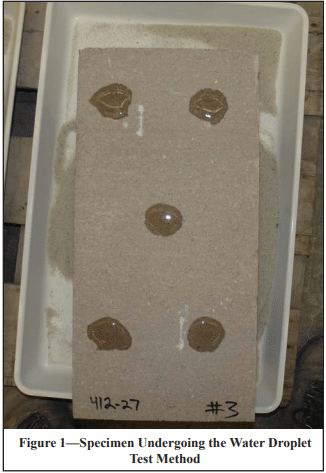
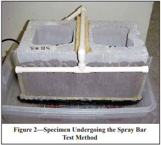
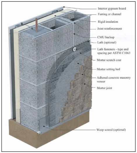
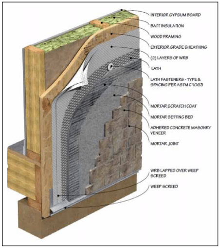
Typical installations are shown in Figures 1 and 2 for concrete masonry and wood frame applications, respectively. There are a number of key installation/inspection points that must be followed to provide a properly performing system. This TEK addresses a number of those key points.

KEY INSTALLATION/ INSPECTION POINTS

1. Substrate Preparation

Wood- and Metal-Framed Applications

According to The Engineered Wood Association’s (APA) Installation of Stucco Exterior Over Wood Structural Panel Wall Sheathing (ref. 1), when wood structural panel sheathing (plywood or oriented strand board – OSB) is used as the substrate material, it must have a in. (3 mm) gap between the sheets on all sides to accommodate wood sheathing expansion when it gets wet. Without the gap, wood swelling will cause the adhered masonry veneer finish to crack, compromising the water resistance of the finish. This will allow water entry and degradation of the substrate, the veneer and the framing. Additionally, the wood framing should be relatively dry at the time of installation, as drying of the wet substrate causes shrinkage which could lead to cracking of the finish. Also note that the International Building Code (ref. 11) limits the deflection of wall systems to L/240 for brittle finishes.

Concrete and Concrete Masonry Walls

Manufactured stone veneer can be directly applied to surfaces of concrete and concrete masonry if they are free of dirt, waterproofing, paint, form oil, or any other substance that could inhibit the mortar bond. They must have a rough texture to ensure a mortar bond. ICRI guideline number 03732 (ref. 5) discusses Concrete Surface Profile (CSP), a standardized method to measure concrete surface roughness. An ICRI CSP equal to or greater than 2 is usually acceptable. Typically, cleaning may be done with power washing and/or mechanical methods (i.e. shot or bead blasting). If a bondable surface cannot be achieved, attach lath and a scratch coat before installing manufactured stone veneer. Do not bond manufactured stone masonry veneer to clay masonry surfaces.

2. Water Management

ASTM C1780, Standard Practice for Installation Methods for Adhered Manufactured Stone Masonry Veneer, (ref. 3) requires two separate layers of water-resistive barrier (WRB) to be installed over wood sheathing in exterior applications. The standard also requires that the two separate layers be installed in shingle fashion. Starting from the bottom of the wall, the inner layer of WRB should be installed, along with flashings, to create a drainage plane. The upper layer of the WRB should lap the top of the lower layer by a minimum of 2 in. (51 mm). The vertical joints of the WRB must be lapped a minimum of 6 in. (152 mm). Inside and outside corners must be overlapped a minimum of 16 in. (406 mm) past the corner in both directions. The WRB should be installed in accordance with the manufacturer’s recommendations and be integrated with all flashing accessories, adjacent WRBs, doors, windows, penetrations, and cladding transitions. The outer layer of WRB is intended to keep the scratch coat from contacting the inner layer of WRB and may be of a different material than the inner WRB.

Drainage Wall Systems: Drainage wall systems also are a very effective means of keeping water from penetrating to the interior and diverting it to the exterior. These systems have a minimum drainage gap of 3/16 in. (5 mm) and a maximum drainage gap of ¾ in. (19 mm). When a system of this type is used, some building codes permit the use of a single WRB.

Other checkpoints for effective water management include:

  1. flashing at all penetrations, terminations and transitions, integrated with the WRB and water directed out of the system,
  2. proper overhang of capping mateials, and
  3. soft joints at dissimilar materials to accommod and soft joints at dissimilar materials to accommodate some movement and minimize incidental water penetration.
3. Proper Selection of Metal Lath by Weight and Style for Each Span and Application

ASTM C1063, Standard Specification for Installation of Lathing and Furring to Receive Interior and Exterior Portland Cement-Based Plaster (ref. 4) must be followed for properly performing manufactured stone veneer system. All lath must be self-furred or use self-furring fasteners to allow the mortar to completely fill and encase the lath.

All lath and lath accessories must be corrosion resistant, consisting of either galvanized or stainless steel materials or nonmetallic lath with a published evaluation report from an ANSI accredited evaluation service and be rated for use behind manufactured stone veneer. More detailed recommendations can be found in the Installation Guide and Detailing Options for Compliance with ASTM 1780 for Adhered Concrete Masonry Veneer (ref. 2).

4. Proper Installation of Metal Lath

The installation of lath should be in accordance with ASTM C1063-14a (current version), Standard Specification for Installation of Lathing and Furring to Receive Interior and Exterior Portland Cement-Based Plaster (ref. 4). Metal lath should be applied horizontally (perpendicular to framing, if present) per manufacturer’s instructions, and should over- lap a minimum of 1 in. (25 mm) at the vertical seams and a minimum of ½ in. (13 mm) at the horizontal seams. The ends of adjoining lath places should be staggered. Lath should be wrapped around inside and outside corners a minimum of 12 in. (305 mm). Lath should be fastened every 7 in. (178 mm) vertically on each stud. The spacing of studs should not exceed 16 in. (406 mm). A similar spacing should be used on concrete or masonry wall surfaces. Do not end lath at inside/outside corner framing.

If not installed in accordance with ASTM C1063, alternate lath installation practices should be in accordance with manufacturer’s instructions. Acceptable installation practices for metal lath should be evaluated in accordance with AC191, Acceptance Criteria for Metal Plaster Bases (Lath) (ref. 12).

While recommendations vary, existing codes and standards do not stipulate the orientation of the lath “cups” (keys) once installed. More important than the orientation of the lath cups is ensuring the lath is embedded within, and bonded to, the mortar scratch coat for a successful AMSV installation. Lath is considered to be embedded within the mortar scratch coat when there is a ¼ in. (6 mm) nominal thickness of mortar between the back plane of the lath and the back plane of the scratch coat for at least one-half (50%) of the surface area of the installation.

When lapping paperbacked lath, be sure that lath is against lath and paper against paper. Paper backing inserted between lath at laps will prevent the mortar from going into the second lath and won’t lock the two sheets together. This can cause cracking in the manufactured stone veneer at the lath joint.

In the summer months, paperbacked lath must be protected from the sun and extreme heat to prevent the glue that attaches the paper to the lath from melting.

5. Proper Fastening of Lath

Proper fastener spacing and penetration is critical. Corrosion resistant fasteners (ref. 4) require a minimum ¾ in. (19.1 mm) nail penetration into wood framing members, a minimum ¾ in. (19.1 mm) staple penetration into wood framing members, or minimum a in. (9.5 mm) penetration of metal framing members. Fasteners must have heads large enough to properly engage the lath.

Note that fasteners must be anchored into the framing members and are to be spaced no more than 7 in. (178 mm) on center per ASTM C1063 (ref. 4). Wood and gypsum sheathing do not have enough holding power to fully support the lath and manufactured stone veneer. A fastener attached only to the sheathing can work loose, particularly if the sheathing becomes wet. Proper fastening will help ensure that the veneer does not become detached during high wind events.

Fastener type and size is also very important. For installation directly to wood framing members, ASTM C1063 allows for the use of  1 ½ in. (38 mm) roofing nails to horizontal framing members. Vertical applications require the use of 1-in. (25-mm) roofing nails, 1-in. (25-mm) staples with minimum ¾-in. (19-mm) crowns, or 6d common nails driven to a penetration of at least ¾ in. (19 mm) and bent over to engage at least three strands of lath.

Where welded or woven wire lath is installed, rest the wire on the fastener for best performance rather than installing the fastener above the wire.

For fastening lath to steel supports, reference is made to ASTM C954 (ref. 6) by ASTM C1063 for screw information. Per that standard, lath can be wire-tied to the member with 18-gauge tie wire. Whether wire or screws are used, the maximum allowed spacing should be maintained, and once again all fastening must be corrosion resistant and penetrate into the structural member. ASTM C954 also states that the screw shall have a minimum head size of 7/16 in. (11 mm) with either a pan or wafer head large enough to engage at least three strands of lath.

6. Clearances

The following minimum clearances are critical to the proper performance of manufactured stone veneer:

Exterior Stud Walls or Where Manufactured Stone Veneer Continues Down a CMU Foundation Wall with WRB and Lath:

     a. 4 in. (102 mm) from grade/earth

     b. 2 in. (51 mm) above paved surfaces such as driveways, patios, etc. This minimum can be reduced to ½ in. (13 mm) if the paved surface is a walking surface supported by the same foundation that supports the wall.

Exterior Concrete or Masonry Walls with or without Lath and Weep Screeds:

      a. 2 in. (51 mm) clearance from grade or ½ in. (13 mm) from a paved surface.

7. Mortar Selection, Mixing and Application
  1. Choose the proper mortar Type for scratch coats and pointing mortars: ASTM C270 (ref. 7) Type N or S for sitemixed or ASTM C1714 (ref. 8) Type N or S for premixed mortar. Setting mortars are the same except that ANSI A118.1 or ANSI A118.4 also may be used (refs. 9, 10)).
  2. Mix the mortar properly and employ hot weather provisions when the ambient temperature is above 90°F (32°C) and cold weather provisions when the temperature is below 40°F (4°C).
  3. Apply the scratch coat with sufficient material and pressure to completely encapsulate the lath with a nominal thickness of ½ in. (13 mm), ensuring that the lath is completely encapsulated with mortar. Horizontally score the surface after the scratch coat is somewhat firm.
  4. If applying to a scratch coat on open studs, non-solid sheathing, or metal building panels, allow the scratch coat to cure 48 hours, then dampen it before applying the setting bed. The setting bed mortar can be applied directly to the scratch coat, to the back of the manufactured stone veneer units (back-buttering), or a combination of both application methods.
8. Setting Manufactured Stone Veneer Units
  1. Dampen the unit’s bonding surface and apply enough setting bed mortar to fully cover the back of the unit with ample squeeze-out between the units.
  2. Take care not to bump previously installed stones. If a unit is inadvertently moved after initial set has begun, it should be removed, mortar scraped off the unit and the scratch coat, and then reinstalled following the application process.
  3. Pay attention to weather conditions and adjust installation procedures for hot or cold weather as needed.
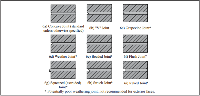
  4. If filled mortar joints are to be provided, add pointing mortar to fill in the joints after there is sufficient cure time of the installed units, when mild contact will not break the bond to the backup system. Tool the pointing mortar when thumbprint hard. Concave or V-groove tooling provides the best water penetration resistance. Filled mortar joints are recommended at schools and other public places as children tend to try climbing walls with unfilled joints.
  5. Clean off remaining mortar debris on the veneer surface with a dry, soft-bristled brush. To prevent mortar smearing, DO NOT use a wet brush to treat uncured mortar joints.
9. Environmental, Chemical, Cleaning and Other Abuse

Avoid exposing manufactured stone veneer to the following as they can result in discoloring or surface damage:

  1. de-icing chemicals, salt, or other harsh chemicals such as acid cleaners and pool chemicals,
  2. sprinklers and roof downspouts should be positioned to prevent frequent moistening of the units, and
  3. avoid installing in areas where the units may be kicked, scraped, or scuffed such as on stair risers.

INSPECTION CHECKLIST

For Wood or Steel Stud Wall Systems:
  • Minimum in. (3 mm) gap between sheathing panels.
  • Minimum of two layers of a water resistive barrier (WRB) for exterior applications.
  • Proper and sufficient lap of WRBs.
  • Fasteners for lath placed into framing members with sufficient penetration.
  • Corrosion-resistant lath, flashing, fasteners, and accessories.
  • Lath cups facing up with at least ¼ in. (6 mm) space to backing.
  • Proper and sufficient lap of lath and no WRB between lath at laps.
  • Scratch coat of proper materials, proper thickness and completely encapsulating lath.
  • Scratch coat scored horizontally after it is somewhat firm.
For Concrete Masonry or Concrete Wall Systems:
  • Use lath if surfaces are not clean and free from release agents, paints and other bond breakers for bonding directly. See checklist items for lath above.
  • If using lath and a WRB is needed, see checklist items for WRB above.
  • If a scratch coat is needed if not using lath, see checklist items for scratch coat above.
For Concrete Masonry, Concrete and Stud Wall Systems:
  • Dampen scratch coat and units before applying setting mortar with full coverage and squeeze-out between units.
  • For placed units inadvertently bumped, remove stones and mortar and reinstall.
  • For filled joints, apply pointing mortar after setting mortar has sufficiently cured. Tool joints when pointing mortar is thumbprint hard.
  • Properly clean pointing mortar debris from veneer surface.

REFERENCES

  1. Installation of Stucco Exterior Over Wood Structural Panel Wall Sheathing. The Engineered Wood Association (APA), 2006.
  2. Installation Guide and Detailing Options for Compliance with ASTM C1780 for Adhered Manufactured Stone Veneer, 5th Concrete Masonry and Hardscapes Association, 2023.
  3. Standard Practice for Installation Methods for Adhered Manufactured Stone Masonry Veneer, ASTM C1780-14. ASTM International, 2014.
  4. Standard Specification for Installation of Lathing and Furring to Receive Interior and Exterior Portland Cement- Based Plaster, ASTM C1063-14a, ASTM International,
  5. Selecting and Specifying Concrete Surface Preparation for Coatings, Sealers, and Polymer Overlays, ICRI Technical Guideline No. 03732. International Concrete Repair Institute, 2009.
  6. Standard Specification for Steel Drill Screws for the Application of Gypsum Panel Products or Metal Plaster Bases to Steel Studs from 033 in. (0.84 mm) to 0.112 in. (2.84 mm) in Thickness, ASTM C954-11. ASTM International, 2011.
  7. Standard Specification for Mortar for Unit Masonry, ASTM C270-14. ASTM International, 2014.
  8. Standard Specification for Preblended Dry Mortar Mix for Unit Masonry, ASTM C1714/C1714M-13a. ASTM International, 2013.
  9. American National Standard Specification for Standard Dry-Set Cement Mortar, 1. American National Standards Institute, 2013.
  10. American National Standard Specification for Modified Dry-Set Cement Mortar, A118.4. American National Standards Institute, 2013.
  11. International Building Code. International Code Council,
  12. Acceptance Criteria for Metal Plaster Bases (Lath), AC191. ICC Evaluation Service, Inc., 2012.
  13.  

Characteristics of Concrete Masonry Units With Integral Water Repellent

INTRODUCTION

A concrete masonry unit’s characteristics are a function of the properties and proportions of the materials used, as well as the manufacturing processes. The unit characteristics do not singularly define the characteristics and performance attributes of a concrete masonry wall, but they certainly play a significant role in influencing those attributes. When used as part of a breathable exterior wall for an inhabited structure, or as a barrier for any conditioned or protected space, concrete masonry is expected to contribute to the water penetration resistance and moisture control of the wall assembly. Current model building codes include provisions intended to ensure that exterior walls provide adequate weather protection for the building (ref. 1).

Design of concrete masonry walls to mitigate or control moisture migration includes many considerations beyond the characteristics of the concrete masonry unit, such as flashing, weeps, workmanship, mortar or grout characteristics, vents, coatings, vapor barriers, air barriers, temperature differences, and accommodation of differential movement, plumbing and roof leaks, as well as other considerations. The potential for condensation, whether at the wall’s interior surface, weather-exposed surface, and/or interior of the wall, should also be considered. Proper design and construction of concrete masonry, considering all of these elements, is critical to the water resistant performance of the wall system. These topics are addressed in References 2 through 7 and in other literature sources.

Mortar joints are especially critical to a wall’s water penetration resistance. Achieving good bond between the mortar and the unit surfaces is essential and is largely influenced by the mortar material itself, tooling procedures, and joint profile as well as by the configuration of the concrete masonry unit. Ribbed units, for example, make it difficult to adequately tool the mortar joints. Reducing mortar’s absorption characteristic is also important for achieving success in moisture control in a concrete masonry wall. This can be achieved using integral water repellent admixtures in the preparation of the mortar.

While all of the aforementioned aspects significantly affect wall performance, this TEK focuses specifically on evaluating the water penetration resistance characteristics of concrete masonry units and their role in contributing to control of moisture in the wall.

THE ROLE OF CONCRETE MASONRY UNITS

The concrete masonry unit’s role and contribution to the concrete masonry wall assembly’s water penetration resistance depends in part on how the units are used in the design. The unit characteristic requirements for contributing to success of the exterior wall may vary depending on the design of the masonry wall in which it is used. For example, the role of concrete masonry units is more critical relative to moisture control when they are part of a weather-exposed surface or exterior wall assembly for a protected and conditioned building than if they are used as an interior wall.

There are three primary forces influencing moisture control of a concrete masonry wall: positive or negative air pressures created by the weather or building ventilation systems, internal moisture absorption and/or adsorption through the matrix of the concrete material, and condensation/evaporation. For the purposes of this discussion, absorption is considered to relate to the cementitious material’s attraction to or affinity for water at the molecular level. Generally speaking, mortar tends to have a much greater affinity for water than does a concrete masonry unit. Adsorption is the affinity of water at the individual surfaces of the cementitious materials. For instance, capillary pressure creates the tendency for water to migrate into a porous object along the surfaces of the interconnected voids, such as a sponge placed in very shallow water. The same tendency may be observed in a mortar joint or an untreated concrete masonry unit due to interconnected voids.

When units are used on a building exterior, it is desirable to limit moisture migration through the first barrier of defense at the wall surface. Wind driven rain can be a significant cause of water breaching a mortar joint, the front face shell of a single wythe wall, or a veneer unit. These weather-induced positive pressures can create a challenge to barrier defenses. As a driving force, they are highest at the surface of the masonry and rapidly diminish a few inches into the mortar joint, the unit, or into the cavity of a drainage wall.

Water repellency characteristics of concrete masonry units can be defined by their contribution to barrier defenses at the surface of the wall (which will help limit the effect of the positive pressure of wind driven rain), by their ability to limit the potential for absorbing and adsorbing moisture through their matrix, and by their contribution to controlling condensation.

PERTINENT UNIT CHARACTERISTICS

Barrier defenses in concrete masonry units can be provided at the surface as well as within the mass of the concrete layer. Surface protection can be enhanced by post-applied breathable materials, external coatings and wall coverings. When coatings are used, the most important characteristic of the unit may be its compatibility with the type of coating used. Some clear sealers and certain paints may not be suitable for a particular concrete masonry unit since some coatings may not be able to bridge open pores or fill all surface irregularities or textures. For example, the proper performance of stucco relies on a rougher and more open unit surface texture of the concrete masonry unit to ensure adequate mechanical bonding.

Beyond the unit’s exterior surface compatibility with the type of breathable post-applied material, coating or wall covering used, if any, an important consideration is the characteristics of the concrete used to produce the unit. The water penetration resistance of concrete is determined by the characteristics of the matrix and its resistance to absorbing moisture. The properties and proportions of the raw materials used to produce the units and the manufacturing procedures employed influence the water penetration resistance of those units. For example, a greater volume of interconnected voids within the unit may provide an easier path for moisture migration. Alternatively, reducing the volume of voids, such as by increasing the unit compaction, may limit moisture movement through the unit. Aggregate type and gradation, cement to aggregate ratio, mix water content, alkalinity, machine compaction, curing processes, and plasticizing and integral water repellent admixtures are some of the parameters that can have an influence on water repellency characteristics.

INTEGRAL WATER REPELLENTS

Integral water repellent admixtures can be used in the mix design of the concrete masonry unit during production to limit a unit’s tendency to absorb moisture through its matrix. Integral water repellent admixtures are usually polymeric products that utilize hydrophobic materials to significantly reduce the absorption characteristics of the concrete. Without these admixtures, even those units with excellent compaction will absorb some moisture through the concrete matrix. Integral water repellents significantly limit absorption by changing the chemistry of the matrix, which may include coating the pores in the concrete with a hydrophobic material that reduces the chemical affinity for water. Thus, concrete masonry units with integral water repellents are positioned to repel water rather than automatically allowing it to migrate through the unit. However, use of integral water repellent admixtures alone does not assure a water-resistant unit. Care must still be taken in production as discussed above to reduce the volume of interconnected voids that will permit moisture migration via other forces, such as wind or gravity.

An advantage of integral water repellent admixtures is that they remain a permanent part of the concrete matrix. Unlike post-applied products, integral water repellent treatments require less maintenance since they are more durable, and they are active throughout the whole concrete matrix and not just at the surface. In addition, integral water repellents can reduce efflorescence by reducing water migration through the concrete masonry (including latent water introduced to the system from grout or mortar).

When integral water repellents are used in concrete masonry units, it is important that the same or a compatible admixture be used in the mortar as well in accordance with manufacturer’s recommendations. Failure to use an integral water repellent admixture in the mortar may compromise the water repellency characteristics of the wall.

EVALUATING UNIT WATER REPELLENCY

The water repellency characteristics of a concrete masonry unit can be evaluated using simplistic field methods or more involved laboratory test methods. Three methods are described briefly below, and in more detail in the referenced published industry test methods (refs. 8, 9, 10).

All of these tests are suitable for evaluating units to be used in wall construction. It is important that field testing, if considered necessary, be conducted prior to wall construction since most of these tests can not be accurately performed on a constructed wall surface. For instance, small amounts of mortar left on the surface of a unit even after cleaning, as well as the cleaning techniques themselves, may alter the surface characteristics of the unit relative to its as-delivered condition. Similarly, water introduced into the system from grout or mortar (water of latency) and in turn absorbed into the unit may change the unit’s characteristics. Before, after, or during construction, accumulated dust or pollution may also alter the surface characteristics. When water repellency characteristics are evaluated prior to unit placement, any unexpected results from field testing can be addressed in a timely manner using the default laboratory test methods described below.

Water Bottle and Water Droplet Tests

The water bottle and water droplet test methods (ref. 8) can be effective as a first pass evaluations of water repellency. The water droplet method is typically conducted on individual units in a horizontal position as shown in Figure 1 (90 degrees to the “as laid” or construction orientation), but as a variation the water bottle test can also be conducted on units placed in a vertical (“as laid”) orientation. Typically, a concrete masonry unit manufactured with an integral water-repellent admixture will be able to support at least three out of the five water droplets for a period of five minutes or more.

At the immediate surface of the concrete masonry unit, the effectiveness of an integral water repellent may diminish over time due to exposure to elements such as dirt, contaminants and UV light. The water repellency characteristics of the concrete just below the surface, however, remain unchanged and provide continuing protection. Therefore, while the water droplet test is rather reliable for identifying a sufficient level of water repellency, it may not be a good indicator of poor water repellency. In other words, if a unit fails to support a droplet of water, the unit should not be considered inadequate, but rather should be taken to a laboratory for further testing using the spray bar and water uptake methods.

If the unit is already installed in the wall, the water bottle test can be used to evaluate the unit. If water applied to the face of the unit is not absorbed immediately, but rather freely runs down the surface of the unit, it likely has sufficient water repellency. Again, if the water is absorbed at the surface, it can not be assumed that the unit does not have sufficient water resistance. Water can be sprayed on a larger wall surface area to determine if isolated units appear to have significantly higher absorption characteristics, since these may appear to have a darker surface color as a result of absorbed water. However, remember that conclusions based upon any field testing, especially on units installed in construction, are not definitive relative to water repellency determinations.

Spray Bar Test

A spray bar test (ref. 9) is a good method to evaluate a unit’s ability to limit absorption as well as verify its effectiveness as a barrier against free moisture migrating through pinholes in the unit face. This laboratory test requires relatively inexpensive equipment and can be conducted in a single day. A spray bar is attached to the unit such that it applies a steady stream of water onto its face (see Figure 2). The inside of a hollow unit is visually inspected to assess if and how moisture has migrated through the front face shell.

Moisture may be present on the interior as dampness that can be seen on the inside surface of the front face shell, on the center or end webs, or even on the interior or exterior surfaces of the back face shell. Moisture may also be observed on the inside of the front face shell from “pinholes.” Pinholes are locations where water has found a path through the face shell to the interior of the unit. Free water will appear as a droplet and may eventually trickle down the inside of the front face shell. A good water repellent unit will limit moisture migration in both forms: dampness and pinholes. If a unit allows an excessive amount of water to migrate through the unit, the type of failure can give an indication of the corrective action that should be taken by the producer. Excessive dampness, for example, may indicate that additional integral water repellent admixture or process adjustment is needed. Excessive pinholes may indicate that an adjustment to the aggregate blend and/or increased compaction may be necessary to reduce the volume of interconnected voids in the unit.

Water Uptake Test

Another good method for evaluating a unit’s resistance to moisture migration is the water uptake test (ref. 10). The test involves placing an oven-dried unit face down (non-split side) in in. (3 mm) of water and measuring the water absorption by means of its weight gain over time.

While the water uptake test may be very good at distinguishing between the levels of resistance to absorption uptake, it will not indicate compaction or other flaws that might result in pinholes. Therefore, it is recommended that the results of this test be used to complement the results of the spray bar test and not used exclusively as a means of evaluation.

REFERENCES

  1. International Building Code, 2003 and 2006 editions. International Code Council, 2003, 2006.
  2. Water Repellents for Concrete Masonry Walls, TEK 19-01, Concrete Masonry & Hardscapes Association, 2006.
  3. Design for Dry Single-Wythe Concrete Masonry Walls, TEK 19-02B, Concrete Masonry & Hardscapes Association, 2012.
  4. Preventing Water Penetration in Below-Grade CM Walls, TEK 19-03B, Concrete Masonry & Hardscapes Association, 2012.
  5. Flashing Strategies for Concrete Masonry Walls, TEK 19-04A, Concrete Masonry & Hardscapes Association, 2008.
  6. Flashing Details for Concrete Masonry Walls, TEK 19-05A, Concrete Masonry & Hardscapes Association, 2008.
  7. Crack Control Strategies for Concrete Masonry Construction, CMU-TEC-009-23, Concrete Masonry & Hardscapes Association, 2023.
  8. Water Droplet Test Method for Concrete Masonry Units, CMHA Method CMU-WR1-07, Concrete Masonry & Hardscapes Association, 2007.
  9. Spray Bar Test Method for Concrete Masonry Units, CMHA Method CMU-WR2-07, Concrete Masonry & Hardscapes Association, 2007.
  10. Water Uptake Test Method for Concrete Masonry Units, CMHA Method CMU-WR3-07, Concrete Masonry & Hardscapes Association, 2007.
  11. Standard Specification for Loadbearing Concrete Masonry Units, ASTM C 90-06. ASTM International, 2006.
  12. Standard Specification for Concrete Facing Brick, ASTM C 1634-06. ASTM International, 2006.

NCMA and the companies disseminating this technical information disclaim any and all responsibility and liability for the accuracy and the application of the information contained in this publication.

Joint Sealants for Concrete Masonry Walls

INTRODUCTION

Successfully sealing joints, such as control joints and around door jambs and window frames, in concrete masonry walls depends on the overall design and construction of the entire building envelope. Movement joints (also called control joints) are needed in some concrete masonry walls to accommodate drying shrinkage, thermal movements, and movements between different building components. Movement joints, joints around fenestration, doors and penetrations, and isolation joints (joints at dissimilar material interfaces) rely on joint sealants to help preserve the overall weather-tightness of the building envelope. In addition, properly sealed joints may be required to meet a specified fire resistance rating or sound transmission class.

The sealant’s primary role is to deform as the joint moves, maintaining the seal across the joint. Most joint sealants are field-applied (as opposed to preformed). For instance, a raked-out mortar joint or open movement joint may receive sealant from a gun-squeezed cartridge, typically applied over a backup material.

This TEK provides a basic overview of joint sealants, installation guidelines to help ensure longevity, and recommended maintenance procedures, based primarily on ASTM C1193, Standard Guide for Use of Joint Sealants (ref. 1) and ASTM C1472, Standard Guide for Calculating Movement and Other Effects When Establishing Sealant Joint Width (ref. 2). This TEK does not address adhesives.

For optimum performance, the sealant must be properly applied to a well-constructed joint. For example, joints that are too thick relative to the width may cause failure of even the best sealant. Detailed information on control joint design and construction is available in CMU-TEC-009-23 (ref. 3).

JOINT SEALANTS AND RELATED MATERIALS

Control joints in concrete masonry construction are classified as butt-joints, where the sealant is exposed to cyclical tension and compression as the joint expands and contracts. Therefore, control joint sealants should be able to maintain their original shape and properties under these conditions. In addition, joint sealants should be impermeable, deformable to accommodate the joint movement, and be able to adhere to concrete and masonry materials or be used with an appropriate primer. The use of primers has been reported to improve bond as well as watertightness at the joint. Because many factors influence a wall’s water penetration resistance, the reader is referred to TEK 19-02B, Design for Dry Single-Wythe Concrete Masonry Walls (ref. 4) for more complete information.

Some variables to consider when selecting a joint sealant are the sealant’s: joint movement capability (typically reported as two percentages, one for elongation and another for compression), time to set-up/cure, adhesion/bond strength to concrete masonry or other substrates, hardness, tensile strength, durability, expected life in service, ease of installation, primer requirements, application temperature range, paintability, warranty requirements, and sag-resistance. Materials that dry out rapidly and/or do not effectively bond to masonry, such as most oil-based caulks, are generally not recommended for use as concrete masonry joint sealants.

In-service conditions for the particular application must also be considered. For example, for joints that are not exposed to the weather, aesthetic factors such as available colors may be more important than the weather-resistance of the joint. Other applications may require properties such as chemical or fire resistance.

In short, no single sealant will meet the requirements of every application. The following sections briefly describe the most common materials used for concrete masonry joints.

Masonry Joint Sealants

Sealants must comply with ASTM C920-11 Standard Specification for Elastomeric Joint Sealants (ref. 6). Sealants used for concrete masonry joints and at penetrations in concrete masonry walls may be polyurethanes, polysulfides, acrylics, silicones, or even modified blends of each. These sealant materials tend to have:

  • high resistance to aging and weathering,
  • good resistance to low-temperature hardening,
  • moderate resistance to age-related hardening,
  • high resistance to indentation,
  • low shrinkage after installation, and
  • nonstaining properties.

Backup Materials

Backup materials are used to: restrict the sealant depth, support the sealant, facilitate tooling, and help resist indentation and sag. They may also serve as a bond breaker, preventing the sealant from adhering to the back of the joint. Backup materials for concrete masonry joints are commonly flexible foams, which are compressed into the joint using hand tools (see Figures 1a and 1b).

Backup materials for control joints must be compressible to accommodate masonry expansion (joint shrinkage), and must recover when the masonry shrinks (joint expands). Because the backup also needs to maintain contact with both joint faces when the joint expands, it is compressed when initially installed. Closed-cell backups should be sized 1 ¼ to 1  the joint width, so they are compressed 25% to 30% when placed in the joint. Open-cell backups, which are less stiff than closed-cell, should be sized 1 ½ times the joint width, so they are compressed about 50% of their undisturbed width when installed.

Bond Breakers

Bond breakers prevent three-sided adhesion of the sealant (i.e. from adhering to the back of a raked joint or to the backup), allowing the sealant to freely deform in response to building movements (see Figure 1c). Because many backup materials act as bond breakers, a separate bond breaker material is not always required. When it is, polyethylene tape, butyl tape, coated papers and metal foils can be used as well as polyurethane, polyethylene and polyolefin foams. Liquid-applied bond breakers are not recommended because of the likelihood of contaminating the sealant adhesion surface.

Primers

Primers, applied to the joint surfaces prior to sealant installation, are sometimes recommended to improve the sealant’s bond strength. In addition, some primers can tolerate application to damp masonry surfaces.

Check the sealant manufacturer’s recommendations for the particular sealant under consideration to determine whether or not a primer should be used on a masonry substrate. To ensure the primer and sealant will be compatible, use the primer recommended by the sealant manufacturer for the sealant being used.

Primer is applied by brush, roller or spray, and typically must dry or cure before sealant application. The recommended elapsed time between primer application and sealant application varies with type of primer, temperature and humidity.

JOINT SEALANT INSTALLATION

Like most materials, joint sealants should be installed in accordance with manufacturer’s instructions. Elements that are due special consideration, such as sealant depth and surface preparation are discussed in more detail below.

It is typically recommended that joint sealants not be applied during rain or snow, and that the masonry be clean and dry at installation. Installation temperature, i.e., the temperature of the masonry when the sealant is applied, may also be a consideration in some cases. Sealants installed at very low temperatures undergo compression as the wall warms up to the mean temperature, while a sealant installed at a high temperature is placed in tension at the mean temperature. For these reasons, it is desirable to have the installation temperature close to the mean annual temperature, although an in- stallation temperature range of 40° to 90°F (4.4 to 32.2°C) is generally considered acceptable for most applications, unless otherwise specified by the sealant manufacturer (ref. 6). Note that the masonry surface temperature may greatly exceed the ambient air temperature, especially on dark-colored and/or south- and southwest-facing walls in the sun.

Sealant Width and Depth

Sealant shape factor refers to the mean width versus mean depth of the sealant as installed in the joint. This ratio is important because it affects the amount of strain the sealant is exposed to as the joint moves, as well as the amount of sealant required to fill the joint (see Figure 1d). Sealants exposed to less strain can typically be expected to have a longer life, all other factors being equal. As illustrated in Figure 2, wider and shallower sealant profiles generally reduce strain and require less sealant.

In the field, sealant shape factor is controlled by varying the depth of the sealant, because the width of the joint is fixed at that point. The depth of sealant in the joint is typically controlled via the use of a backup material. Sealants that have a higher depth to width ratio tend to stretch more readily with joint movement, whereas with lower ratios the tendency is for the sealant to tear when subjected to movement. In general, for joint widths from ¼ to ½ in. (6 to 13 mm) the joint depth should be no more than the width of the joint. After the sealant is tooled, the minimum thickness of the sealant at the midpoint of the joint opening should not be less the in. (3 mm) and the sealant adhesion dimension no less than ¼ in. (6 mm) (refs. 1, 2). The required thicknesses also should be verified with the sealant manufacturer.

Joint Preparation

For all control joints, mortar should be raked out of the vertical joints on both sides of the panels. The mortar should be raked out at least ¾ in. (19 mm) to allow for a backup material and sealant ( in. (9.5 mm) if no backing is used). This also assures a plane of weakness at the control joint. Mortar in the control joint may also be totally omitted to ensure freedom of movement.

Proper surface preparation prior to sealant installation improves bond between sealant and masonry, and minimizes adhesion failures. Follow the sealant manufacturer’s recommendations regarding cleaning and/or priming the concrete masonry surface prior to applying sealant.

Backup materials must be installed to the proper depth in the joint to control the depth of sealant. Tools for placing backer materials can help ensure correct placement. Any tools used for placement should have a smooth surface adjacent to the backup, to avoid puncturing or otherwise damaging the backup material during placement.

Applying Sealant

Sealants may be either single- or multi-component. Multi-component sealants require thorough mixing, in accordance with the manufacturer’s instructions, to ensure uniform curing and to avoid over-mixing. Once mixed, the sealant has a limited pot life, so batch sizes should be matched to what can be installed within the pot life.

Masonry joint sealants are typically installed using a common caulk gun, with a tip the same size as the width of the joint. The caulk gun should be held at an angle of about 45° to the wall face, and moved slowly and consistently. Filling joints from bottom to top helps avoid trapping air as the sealant is placed.

Immediately after the joint is filled, the sealant should be tooled to a concave shape. Tooling helps ensure intimate contact between the sealant and masonry, consolidates the sealant, provides a concave profile and improves the appearance of the joint. The hour-glass shape shifts peak stresses away from the adhesion surface and to the middle of the sealant joint during joint movement. Most sealant manufacturers recommend dry-tooling for the best results.

MAINTENANCE

Properly maintained joint sealants will help maintain the water penetration resistance of the building envelope. Sealant materials cannot be expected to have the same life as a masonry building. For this reason, the sealant condition should be inspected on a regular basis, perhaps when the facade is cleaned, and repairs made as needed. Manufacturer’s recommendations should be used as a guideline to estimate sealant life. However, sealant life will vary greatly with exposure and the quality of the initial installation.

Because joint sealant adheres better to properly prepared surfaces, the old or deteriorated sealant should be completely removed from the joint and the joint cleaned prior to reapplication. Minor repairs can be made by cutting out the defective area and reapplying sealant of the same type. Sealants can be removed using a sharp knife to sever the sealant from the masonry. Although some manufacturers recommend more aggressive cleaning methods, such as sand-blasting or grinding, care should be taken when using these methods. For more detailed information on sandblasting, see TEK 08-04A, Cleaning Concrete Masonry, (ref. 6).

Once the joint is properly prepared, sealant can be installed as described above for new construction.

REFERENCES

  1. Standard Guide for Use of Joint Sealants, ASTM C1193-13. ASTM International, 2013.
  2. Standard Guide for Calculating Movement and Other Effects When Establishing Sealant Joint Width, ASTM C1472-10. ASTM International, 2010.
  3. Crack Control Strategies for Concrete Masonry Construction, CMU-TEC-009-23, Concrete Masonry & Hardscapes Association, 2023.
  4. Design for Dry Single-Wythe Concrete Masonry Walls, TEK 19-2B, Concrete Masonry & Hardscapes Association, 2012.
  5. Standard Specification for Elastomeric Joint Sealants, ASTM C920-11. ASTM International, 2011.
  6. Cleaning Concrete Masonry, TEK 8-4A. National Concrete Masonry Association, 2005.

Flashing Details for Concrete Masonry Walls

INTRODUCTION

At critical locations throughout a building, moisture that manages to penetrate a wall is collected and diverted to the outside by means of flashing. The type of flashing and its installation may vary depending upon exposure conditions, opening types, locations and wall types. This TEK includes typical flashing details that have proven effective over a wide geographical range. The reader is also encouraged to review the companion TEK 19-04A Flashing Strategies for Concrete Masonry Walls (ref. 1) which addresses the effect of moisture on masonry, design considerations, flashing materials, construction practices, and maintenance of flashing.

CAVITY WALLS

For cavity walls, as illustrated in Figure 1, the cavity typically ranges from a minimum of 2 in. to a maximum of 4 ½ in. (25 to 114 mm) wide, with a minimum of a 1 in. (25 mm) clear airspace if rigid insulation is placed in the cavity. Cavities wider than 4 ½ in. (114 mm) are permitted only if a detailed analysis is performed on the wall ties per the International Building Code and Building Code Requirements of Masonry Structures (refs. 2, 3) The 1 in. (25 mm) clear airspace works only if the mason takes precautions to insure that mortar will not bridge the airspace. Such precautions would include beveling the mortar bed away from the cavity or drawing a piece of wood up the cavity to collect mortar droppings. If precautions are not taken, it is suggested that a wider airspace be utilized, i.e. 1½ to 2 in (38 to 51 mm). Also when using glazed masonry veneer, a 2 in. (51 mm) minimum airspace is recommended with air vents provided at the top and bottom of the wall because of the impermeable nature of the unit. Proprietary insulated drainage boards or mats are available that provide an unobstructed drainage path that eliminate the need for a clear airspace (ref. 4).

As shown in Figure 1, the flashing in a cavity wall at the intersection of the foundation should be sealed to the exterior faceshell of the backup wythe, project downward to the foundation surface, outward to the exterior face of the wall, and terminate with a sloped drip. Weep holes or open head joints should be located a maximum of 32 in. (813 mm) apart. Flashing at lintels and sills (shown in Figures 2 and 3, respectively) is very similar. Although not shown, vents can be installed in the vertical head joints at the top of masonry walls to provide natural convective air flow within the cavity to facilitate drying. Prefabricated flashing boots available for both single and multiwythe walls are shown in Figure 7.

SINGLE WYTHE WALLS

Flashings in single wythe walls, like cavity walls should be positioned to direct water to the exterior. This is normally accomplished using two narrower units to make up the thickness of the wall and placing flashing between them as shown in Figures 4 and 8. Care should be exercised to insure that surfaces supporting the flashing are flat or are sloping to the exterior. This can be accomplished by using solid units, lintel or closed bottom bond beam units turned upside down similar to Figure 3, or by filling cells of hollow units with mortar or grout.

Flashing of single wythe walls at lintels, foundations, and bond beams is accomplished in the same manner as shown in Figure 4 while sills are shown in Figure 6. Through-wall flashing is used in many areas of the country as shown in Figure 9. However, the bondbreaking effects of this type of detail need to be evaluated in regard to the structural performance of the wall. Additional information for flashing single-wythe walls, particularly architectural concrete masonry walls, and means for providing a higher level of structural continuity at flashings is contained in TEK 19-02B (ref. 5). Flashing single wythe walls at the ends of bar joists which utilize wall pockets for bearing is shown in Figures 8 and 8a.

FLASHINGS AT COPINGS AND CAPS

The type of flashing detail to use on low-sloped roofs will in part depend on the type of roofing membrane being used. As with any flashing detail, the materials used should result in a uniform and compatible design. For example, joining two materials with significantly different coefficients of thermal expansion (such as metal flashing and bitumen roofing membrane) can cause tearing and failure of the joint. Many roofing membranes also shrink as they age. As a result, roofing membranes extending over the top of a parapet may pull the parapet off the wall as the roofing membrane shrinks. Counter flashing provides a solution to these problems as shown in Figure 8. Counter flashing also facilitates the reroofing process by allowing easy removal and access to the flashing membrane fasteners.

During placement of the final courses of masonry in parapets, and commencing with the second course below the coping/cap location, a grout stop should be placed over cores so that grout can be placed for the positioning of anchor bolts (Figure 8).

In coping installations it is imperative that penetrations of through-wall flashing be tightly sealed to prevent water infiltration. A full mortar bed is required to be placed on the through-wall flashing to allow proper positioning of coping units. Full head joints are placed between the coping units as well as properly spaced control joints. The joints between the coping units should then be raked and a joint sealant applied.

Coping units should be sized such that overhangs and a drip reveal are provided on both sides of the wall. Metal caps require wood plates for anchorage, which in turn are usually attached to the wall with anchor bolts. The cap should be sloped to prevent water from draining onto the exposed surface of the masonry and should extend at least 4 in. (102 mm) over the face of the masonry and sealed on both sides. Smooth face or uniform split face CMU should be considered for use under the cap to ensure a relatively tight fit between the masonry and cap that might be hindered by uneven concrete masonry units such as split-face or fluted units.

INTERIOR WALL TREATMENTS

Concrete masonry walls with an interior treatment may also utilize a through-wall flashing installation of flashings as shown in Figure 9. However, as noted in the figure, through-wall flashings generally create a bond-breaker, which reduces the structural capacity of a masonry wall. This effect should be carefully evaluated before implementing this type of detail particularly in high-wind and seismic areas.

As shown in Figure 9, the flashing should project through the wall and be carried up on the interior concrete masonry surface. Furring strips installed to receive the plastic vapor retarder and the interior gypsum board will hold the flashing in position. This procedure permits any water that may penetrate to the interior surface of the concrete masonry wall to drain out at the base of the wall. Weep holes should project completely through the wall thickness. Vents, if used, should project into the core areas only.

SPLICING FLASHING

When it is necessary to splice the flashing, extra precautions are required to ensure that these discreet locations do not become sources of water penetration. Flashing should be longitudinally continuous or terminated with an end dam as shown in Figure 7. The splicing of flashing materials consisting of plastic and rubber compounds is acheived by overlapping the joint a minimum distance of 4 in. (102 mm). The lapped area is then bonded together with adhesive if the flashing material is not self-adhering.

Lap splicing of metal flashing is not recommended as it has a different coefficient of thermal expansion than that of concrete masonry. As the temperature fluctuates, the flashing material will expand and contract differently than the masonry material, which can result in sealant failure and a potential point of entry for moisture. A typical flashing splice is detailed in Figure 10. Here, two sections of sheet metal type flashing that are to be spliced are first installed with a ¼-in. (6.4 mm) gap between them to allow for expansion of the flashing. Next, a section of pliable self-adhering membrane (such as rubberized-asphalt) or other pliable membrane set in mastic is fully bonded to the flashing at the location of the gap.

REFERENCES

  1. Flashing Strategies for Concrete Masonry Walls, TEK 1904A, Concrete Masonry & Hardscapes Association, 2008.
  2. International Building Code. International Code Council, 2003 and 2006.
  3. Building Code Requirements for Masonry Structures, ACI 530/ASCE 5/TMS 402, reported by the Masonry Standards Joint Committee, 2002 and 2005.
  4. Flashing…Tying the Loose Ends, Masonry Advisory Council, Chicago, IL, 1998.
  5. Design for Dry Single-Wythe Concrete Masonry Walls, TEK 19-02B, Concrete Masonry & Hardscapes Association, 2012.
  6. Generic Wall Design, Masonry Institute of Michigan, 1998.


Flashing Strategies for Concrete Masonry Walls

INTRODUCTION

The primary role of flashing is to intercept the flow of moisture through masonry and direct it to the exterior of the structure. Due to the abundant sources of moisture and the potentially detrimental effects it can have, the choice of flashing material, and the design and construction of flashing details, can often be as key to the performance of a masonry structure as that of the structural system.

The type of flashing material to be used is governed by both environmental and design/build considerations. Environmental considerations include such factors as the physical state of moisture present (liquid, solid, or vapor), air movement, and temperature extremes as well as temperature differentials. Design/build considerations include the selection of the proper type of flashing material, location of the flashing, structural, and installation details. Drawings for flashing details, often the only method of communicating the necessary information between the designer and contractor, should be comprehensive and show sufficient detail for the proper interpretation and installation of flashing systems. TEK 19-05A Flashing Details for Concrete Masonry Walls (ref. 3) includes such details.

Although flashing is the primary focus of this TEK, it should be understood that the role of vapor retarders, air barriers, and insulation are also important elements to consider for any wall design as the performance of the entire system can be dependent on the design of its individual components.

EFFECT OF MOISTURE ON MASONRY

The damage caused to a masonry structure (or its contents) due to the infiltration of moisture can take many forms, depending on the source and the physical state of the water. For example, in the liquid state, water penetrating to the interior of a building may cause considerable damage to its contents. In some extreme cases, water trapped within the masonry may freeze, inducing spalling and cracking of the masonry units or mortar. Alternatively, water vapor can lead to condensation inside the cores and on the surfaces of masonry if the dew point temperature is reached. During cold weather, below 28 °F (-2 °C), water vapor can accumulate on a cold surface and form frost or increase the quantity of ice within the masonry.

Although it is commonly thought that moisture problems stem only from the external environment, this is not always the case. For example, in some instances it is possible for the humidity of interior air to cause water damage to the exterior of a structure. This damage may appear in the form of water stains, ravelled mortar joints, spalled surfaces, or efflorescence.

DESIGN CONSIDERATIONS

Water Movement

In the design of any structure, the presence and movement of water in any of its three forms needs to be considered. Significant forces that influence water movement include wind pressure, gravity, and moisture absorption by the material. Dynamic wind pressure on the surface of an exposed wall can drive exterior moisture (in the form of rain or irrigation water) into the masonry. Gravity, which is always present, draws the free water vertically downward, while the absorptive characteristics of the masonry can cause moisture migration in any direction by capillary action.

It should also be recognized that these forces do not act independently of one another. For example, wind-driven rain may enter masonry through cracks at the interface between mortar and units and migrate downward through the wall due to the force of gravity, or it may be transferred horizontally through the wall either by pressure or by flowing across the webs of the units or mortar bridges. Wind-driven rain can also be absorbed by masonry units and carried from the exterior surface to the interior surface by capillary action. Additionally, ground water may be drawn upward by the wicking action of units placed on porous foundations or by contact with moist soil.

Designers should never assume that any material is capable of rendering a wall totally impervious to water penetration. Surface treatments, designed to reduce the quantity of water entering a masonry structure, are helpful in this regard but should not be considered as a sole means of protection. Available as clear and opaque compounds, the effectiveness of surface treatments depends on their composition and compatibility with the masonry. They also do not reduce the movement by capillary action (wicking) of any water that does penetrate the masonry face through cracks or defects in the mortar/masonry.

The use of integral water repellent admixtures in concrete masonry units and mortars can also reduce the amount of water entering the masonry. In addition, they inhibit water penetrating the masonry face from wicking to the back face of the wall.

Proper selection and application of surface treatments and integral water repellents can greatly enhance the water resistant properties of masonry, but they should not be considered as substitutes for flashing. See TEKs 19-01 and 19-02B (refs. 8 and 2) for more information on water repellents for concrete masonry.

Flashing Location

The proper design of masonry for resistance to water penetration includes consideration of the various types of wall construction such as single wythe, cavity, veneer, etc. During the design phase it should be understood that all exterior masonry walls may be subjected to some degree of water penetration and/or water vapor movement during its design life. Flashing is recommended for all locations where moisture may potentially penetrate into a wall and where the free drainage of water is blocked. Some of these critical locations include the top of walls and parapets, at all horizontal obstructions such as over openings, beneath sills, above shelf angles, at the base of walls, and in walls at ground level to serve as a moisture retarder to reduce the amount of water wicked up into the masonry above grade.

When selecting the flashing material for a particular application, the service conditions, projected life of the structure, and past performance characteristics of the flashing materials should be reviewed. Flashing should be designed to perform satisfactorily for the design life of the building since repair or replacement can be very labor intensive and expensive.

FLASHING MATERIALS

A wide variety of flashing materials are available. The selection of the type of flashing material to use can be influenced by several factors including cost, durability, compatibility with other materials, ease of installation, aesthetic value, and performance. Table 1 summarizes some of the attributes for various flashing materials. The advantages and disadvantages of each must be weighed for each individual project to provide the most cost-effective and desirable choice.

Prefabricated flashing boots may be available for inside and outside corners and end dams. These boots eliminate the need for cutting, folding, or tucking the flashing materials at these locations. However, due to construction tolerances, some of these prefabricated items, particularly those of rigid materials, may be difficult to fit into their intended location.

Sheet Metals

Stainless steel is technically any of a large and complex group of corrosion resistant iron chromium alloys possessing excellent weather and chemical resisting properties. Preformed sections must be properly sized so that on site modification is minimized. Stainless steel flashing with a conventional annealed finish should comply with Standard Specification for Stainless and Heat-Resisting Chromium-Nickel Steel Plate, Sheet, and Strip, ASTM A 167 (ref. 6). Generally, Type 304 stainless steel with a minimum thickness of 0.010 in. (0.25 mm) is satisfactory. Lap sections require solder conforming to Standard Specification for Solder Metal, ASTM B 32 (60% tin and 40% lead) (ref. 5). Stainless steel drip edges used in combination with other flashing materials offer an economical compromise with a durable drip edge.

Copper is a nonferrous metal possessing good ductility and malleability characteristics. Like stainless steel, it also possesses excellent weather and chemical resistant properties. Preformed sections or sheet materials are easily modified to conform to site requirements. However, it should be cautioned that once weathered, copper flashings produce a green patina that may impart a green stain to adjacent masonry surfaces that some find objectionable.

Galvanized steel is less expensive than stainless steel but is subject to corrosive attack from salts and acids. The galvanized coating also may crack at bends, lowering the corrosion resistance. As with stainless steel, it is also difficult to form and to solder laps effectively.

Composites

Combinations of metals and plastics are supplied by some dealers. The composition and application of these combined materials should be determined before use. Composites utilizing copper are the most popular since they combine the durability and malleability of copper with the nonstaining characteristics of a protective coating. Composites containing aluminum should be avoided.

Plastics and Rubber Compounds

Plastics are categorized as polymeric materials of large molecular weight, usually polyvinyl chloride (PVC) or polyethylene. Manufacturers of plastic flashings should be consulted for documentation establishing the longevity of the plastic in a caustic environment (pH = 12.5 to 13.5), the composition of the plastic, ease of working at temperatures ranging from 20 to 100 °F (-7 to 38 °C), and ability to withstand exposure to ultraviolet light.

Ethylene Propylene Diene Monomer (EPDM) is a synthetic rubber that is used as a single ply roofing membrane as well as flashing. It has better low temperature performance than PVC and will not embrittle. It offers ultraviolet light and ozone resistance and can be left exposed.

Self-adhering, rubberized asphalt membranes consist of a composite of flexible plastic film for puncture and tear resistance combined with a rubberized asphalt adhesive layer. This material adheres to itself, requiring less effort to seal laps or corners which speeds installation. It also self-adheres to the substrate which prevents water from migrating under the flashing and is self-healing in the event of punctures. However, it should not be applied to damp, dirty, or dusty surfaces and typically has a lower installation temperature limit of 25 °F (-4 °C). Because it degrades in the presence of extended UV exposure, it should not be left exposed and requires a metal drip edge.

CONSTRUCTION PRACTICES

To perform, flashing must be designed and installed properly or it may aggravate rather than reduce water problems. Flashing should be longitudinally continuous or terminated with end dams. Longitudinally continuous requires that joints be overlapped sufficiently, 4 in. (102 mm) minimum, to prevent moisture from entering between the joints and they must be bonded (joined) together with adhesive if they are not self adhering to prevent water movement through the lap area. With metal flashings a ¼ in. (6.4 mm) gap joined and sealed with a pliable membrane helps in accommodating expansion (ref. 3).

Flashings should be secured at the top by embedment into the masonry, a reglet, or should be adhesively attached so that water cannot infiltrate or move behind the attachment. For multi-wythe construction, the flashing should project downward along the outer surface of the inner wythe and then project outward at the masonry joint, shelf angle, or lintel where it is to discharge the water. Every effort should be made to slope the flashing towards the exterior. Effectively placed mortar or sealant material can help promote this drainage. The flashing should continue beyond the exterior face of the masonry a minimum of ¼ in. (6.4 mm) and terminate with a sloped drip edge.

An additional design consideration for flashings includes ensuring that all materials are compatible. For example, contact between dissimilar metals can result in the corrosion of one or both of the metals. Additionally, the coefficients of thermal expansion for the flashing and masonry materials differ. All flashing details should be designed to accommodate the resulting differential movement.

Other recommended practices involve the use of tooled concave mortar joints to reduce water penetration through the mortar joints. Masons should be careful to ensure that mortar dropped onto the flashing is minimized. This can be accomplished by beveling the mortar on the face shells adjacent to the cavities in cavity wall construction. In addition, cavity drainage mats, gravel beds, screens, or trapezoidal drainage material (filter paper) can be used to prevent mortar droppings from collecting on the flashing, which can form dams and block weep holes. Mortar collection devices at regular intervals or filling the cells with loose fill insulation a few courses at a time as the wall is laid-up, can be effective in dispersing minor mortar droppings enough to prevent clogging.

Weep holes, the inseparable companion to flashings, should provide free movement of water out of the concrete masonry cores, collar joints, or cavities. Any construction practice that allows forming the weep holes without inhibiting water flow may be used. Cotton sash cords and partially open head joints are the most common types of weep holes. Cotton sash cords should be removed prior to putting the wall into service to provide maximum unobstructed drainage. If necessary, insects can be thwarted by inserting stainless steel wool into the openings or using plastic or metal vents.

Vents

Weep holes often serve a dual function, first for water drainage and second as vents. Vents are desirable in some masonry wall systems to help reduce the moisture content of the masonry during drying periods. Air circulation through the cores and cavities within the masonry promotes equalization of moisture content throughout the masonry. Vents are considered desirable where air is confined within masonry, such as in parapets or areas of high humidity such as natatoriums.

MAINTENANCE

Maintenance programs should involve preserving the “as-built” design documents, records pertaining to inspections during the life of the structure, and continuing appraisal of the performance of the structure in addition to conventional repair and upkeep. Documentation of inspections, if efflorescence and water stains are observed, and logs of reported water penetration and their identified location, assist in determining proper corrective actions. Pictures with imprinted dates are suggested.

Knowledge of the wall design and construction can influence repair decisions. If flashing and weep holes were omitted during construction, it may prove effective to simply drill weep holes and vents to promote drainage and drying. Weep holes so drilled should be either at the intersection of the bed and head joints or into the cores at the bottom of the wall. Vents should be installed at the top of the wall or directly below bond beams. See TEK 08-01A Maintenance of Concrete Masonry Walls (ref. 4) for more detailed information on maintenance of concrete masonry walls.

When considering maintenance options, it is important to ensure that a masonry wall’s moisture control measures are kept intact. Thus, applying sealant beads, pargings, or coatings to a wall should be carefully weighed. Weep holes and vents should be maintained in an open condition to allow evacuation of moisture.

SUMMARY

Flashings are essential at foundations, bond beams, above and below openings, at shelf angles and at copings. Weep holes and vents reduce the moisture content of masonry walls. Proper selection of flashing materials, proper detailing, and proper installation will help ensure satisfactory performance.

REFERENCES

  1. The Building Envelope: Solutions to Problems, Proceedings from a national seminar series sponsored by Simpson Gumpertz & Heger Inc., 1993.
  2. Design for Dry Single-Wythe Concrete Masonry Walls, TEK 19-02B, Concrete Masonry & Hardscapes Association, 2012.
  3. Flashing Details for Concrete Masonry Walls, TEK 19-05A, Concrete Masonry & Hardscapes Association, 2008.
  4. Maintenance of Concrete Masonry Walls, TEK 08-01A, Concrete Masonry & Hardscapes Association, 2004.
  5. Standard Specification for Solder Metal, ASTM B 32-04, ASTM International, 2004.
  6. Standard Specification for Stainless and Heat-Resisting Chromium-Nickel Steel Plate, Sheet, and Strip, ASTM A 167-99(2004), ASTM International, 2004.
  7. Through-Wall Flashing, Engineering and Research Digest No. 654, Brick Industry Association.
  8. Water Repellents for Concrete Masonry Walls, TEK 19-01, Concrete Masonry & Hardscapes Association, 2006.


Preventing Water Penetration in Below-Grade Concrete Masonry Walls

INTRODUCTION

Concrete masonry has traditionally been the material of choice for foundation wall construction. State-of-the-art waterproofing, dampproofing, and drainage systems applied to concrete masonry provide excellent protection from water penetration, ensuring protection for building contents and comfort for occupants.

Protecting below-grade walls from water entry involves installing a barrier to water and water vapor. Below grade moisture tends to migrate from the damp soil to the drier area inside the basement. An impervious barrier on the exterior wall surface can prevent moisture entry. The barrier is part of a comprehensive system to prevent water penetration, which includes proper wall construction and the installation of drains, gutters, and proper grading.

WATERPROOFING AND DAMPPROOFING

Building codes (refs. 1, 2) typically require that basement walls be dampproofed for conditions where hydrostatic pressure will not occur, and waterproofed where hydrostatic pressures may exist. Dampproofing is appropriate where groundwater drainage is good, through granular backfill into a subsoil drainage system.

Hydrostatic pressure may exist due to a high water table or due to poorly draining backfill, such as heavy clay soils. Materials used for waterproofing are generally elastic, allowing them to span small cracks and accommodate minor movements.

When choosing a system, consideration should be given to the degree of resistance to hydrostatic head of water, absorption characteristics, elasticity, stability in moist soil, resistance to mildew and algae, and impact, puncture and abrasion resistance.

WATERPROOF AND DAMPPROOF SYSTEMS

Waterproof and dampproof systems must be continuous to prevent water penetration. Similarly, the barrier is typically carried above the finished grade level to prevent water entry between the barrier and the foundation wall. Cracks exceeding ¼ in. (6 mm) should be repaired before applying a waterproof or dampproof barrier. Repair of hairline cracks is typically not required, as most barriers will either fill or span small openings. In addition, most waterproofing and dampproofing systems should be applied to clean, dry walls. In all cases, manufacturer’s directions should be carefully followed for proper installation.

Particular attention should be paid to wall penetrations and to re-entrant corners at garages, porches, and fireplaces. Because differential movement often occurs at these intersections, stretchable membranes are often used to span any potential cracks. Alternately, the main wall in some cases can be coated prior to constructing the cross wall provided that structural adequacy is maintained.

Coatings are sprayed, trowelled, or brushed onto below-grade walls, providing a continuous barrier to water entry. Coatings should be applied to clean, structurally sound walls. Walls should be brushed or washed to remove dirt, oil, efflorescence, or other materials which may reduce the bond between the coating and the wall.

Sheet membranes and panels are less dependent on workmanship and surface preparation than coatings. Many membrane systems are better able to remain intact in the event of settlement or other foundation wall movement. Seams, terminations, and penetrations must be properly sealed.

Prescriptive Systems

Both the International Building Code (IBC) (ref. 1) and the International Residential Code (IRC) (ref. 2) include prescriptive methods for waterproofing and dampproofing. Except where a damproofing material is approved for direct application to the masonry, masonry walls are required to have not less than in. (9.5 mm) portland cement parging applied to the exterior of the wall before applying damproofing. The following materials are specified in the IBC as acceptable waterproofing and dampproofing materials:

  • two-ply hot-mopped felts;
  • 6 mil (0.006 in.; 0.152 mm) or greater polyvinyl chloride;
  • 40 mil (0.040 in.; 1.02 mm) polymer-modified asphalt;
  • 6 mil (0.006 in.; 0.152 mm) polyethylene; or
  • other approved methods or materials capable of bridging nonstructural cracks.

In addition, the IRC includes the following materials for concrete and masonry foundation waterproofing:

  • 55 pound (25 kg) roll roofing;
  • 60 mil (1.5 mm) flexible polymer cement;
  • in. (3 mm) cement-based, fiber-reinforced, waterproofing coating; or
  • 60 mil (1.5 mm) solvent-free liquid-applied synthetic rubber.

Both the IBC and IRC list the following materials as acceptable for dampproofing only (note—any of the waterproofing materials are acceptable for dampproofing):

  • bituminous material;
  • 3 lb/yd² (16 N/m²) of acrylic modified cement;
  • in. (3.2 mm) coat of surface-bonding mortar complying with ASTM C887 (ref. 3); or
  • other approved methods or materials.

The following discusses details of some of the prescriptive code methods for waterproofing and dampproofing.

Rubberized Asphalt Systems

A wide variety of rubberized and other polymer-modified asphalt waterproofing systems are available. Most of these are applied as sheet membranes, although some are available as liquid coatings. These systems provide a continuous barrier to water with the ability to elastically span small holes or cracks.

Rubberized asphalt sheet membranes are applied over a primer, which is used to increase adhesion of the sheet. The membrane is adhesive on one side and protected by a polyethylene film on the other. Adjacent pieces of membrane must be lapped, and the top and bottom edges sealed with mastic to provide continuous protection from water entry. After the membrane is placed on the wall, the surface is rolled with sufficient pressure to ensure adequate adhesion.

Rubberized asphalt is also available in a form that can be melted at the jobsite, then spread to completely cover foundation walls. Liquid coatings can be applied by airless spray, roller, or brush. Both the liquid-applied and sheets are covered with a protection board, which protects from construction traffic and during backfilling.

Cementitious Coating Systems

Cement-based coatings are typically trowelled onto concrete masonry walls or brushed on using a coarse-fibered brush. The coatings sufficiently fill block pores, small cracks, and irregularities. Some cementitious coatings are modified with various polymers to increase elasticity and water penetration resistance.

Elastomeric Systems

Elastomeric materials are acrylic-based products which provide a flexible barrier to water penetration for below grade walls. Elastomerics are available as liquid coatings and as sheet membranes. The sheets are attached with adhesive, and may be reinforced with fabric to further increase tensile strength and resistance to tears and punctures. Liquid coatings can be applied by airless spray, roller, or brush.

Other Waterproofing and Dampproofing Systems

The systems listed above (and within the building codes) are only some of the materials and systems available; several others are discussed below. See Basement Manual—Design & Construction Using Concrete Masonry (ref. 4) for more detailed information.

Parging and Bituminous Coating Systems

Where drainage is good, a dampproof coating of parging with a permanent bituminous coating has proven to be satisfactory. A portland cement and sand mix (1:3.5 by volume), or Type M or S mortar may be used for the parge coat. The parge coat should be beveled at the top to form a wash, and thickened at the bottom to form a cove between the wall base and top of footing, as shown in Figure 1.

To further increase water penetration resistance, a bituminous coating is applied over the parging. Coal tar or asphalt based bitumens are available in solvent for hot application, or in emulsions for application at ambient temperatures. These coatings can be sprayed, brushed, or trowelled onto the finish coat of parging.

Bentonite Panel Systems

Bentonite is a mineral that swells to many times its original size when wet. Waterproofing panels incorporate dry bentonite encased in kraft paper or fabric. After installation, the bentonite swells up the first time it is exposed to water, expanding between the foundation wall and the backfill, and forming an impervious barrier. The swelling seals small cracks in the foundation wall or punctures in the panels themselves.

To prevent premature hydration bentonite panels must be protected from moisture until they are properly installed and the foundation wall has been backfilled.

Other Systems

There are several systems for which Acceptance Criteria, developed by the ICC Evaluation Service, exist. Cold, liquid-applied, below-grade exterior dampproofing and waterproofing materials should demonstrate compliance with ICC ES AC29 (ref. 5). For rigid, polyethylene, below-grade dampproofing and waterproofing materials, compliance should be shown to ICC-ES AC114 (ref. 6).

Some systems fulfill the requirements of both waterproofing/dampproofing and wall insulation. These systems, however, may not be specified directly in the building code or have an Acceptance Criteria. In these cases, materials should be evaluated both for general waterproofing (or dampproofing) characteristics (such as resistance to hydrostatic pressure, etc.) as well as for criteria specific to the material or system. The Acceptance Criteria listed above can be used as a baseline for a material, although not all requirements may apply to all materials. An engineering evaluation of the product testing results can demonstrate acceptable performance for use as dampproofing or waterproofing.

DRAINAGE

Draining water away from basement walls significantly reduces the pressure the basement wall must resist. This reduces both the potential for cracking and the possibility of water penetration into the basement if there is a failure in the waterproof or dampproof system.

Perforated pipe or drain tiles laid with open joints have proven to be effective at collecting and transporting water away from foundation walls. The invert of drain pipes should be below the top of the floor slab elevation, as shown in Figure 1. The backfill drain should be connected to solid piping to carry the water to natural drainage, a storm sewer, or a sump. For adequate drainage, drains should slope at least in. in 10 ft (10 mm in 3 m).

Drain tile and perforated pipes are typically laid in crushed stone to facilitate drainage. At least 2 in. (51 mm) of washed gravel or free-draining backfill (containing not more than 10% material finer than a No. 4 sieve) should be placed beneath perforated pipes. Drain tiles laid with open joints are more effective when laid on the undisturbed soil where the water begins to accumulate. At least 6 to 12 in. (152 to 305 mm) of the same stone should cover the drain and should extend 12 in. (305 mm) or more beyond the edge of the footing. To prevent migration of fine soils into the drains, filter fabrics are often placed over the gravel.

Drainage pipes may also be placed beneath the slab and connected to a sump. In some cases, pipes are cast in or placed on top of concrete footings at 6 to 8 ft (1.8 to 2.4 m) o.c. to help drain water from the exterior side of the foundation wall.

The backfill material itself also significantly affects water drainage around the wall. The backfill material should be well-draining soil free of large stones, construction debris, organic materials, and frozen earth. Saturated soils, especially saturated clays, should generally not be used for backfill, since wet materials significantly increase the hydrostatic pressure on foundation walls. The top 4 to 8 in. (102 to 203 mm) of backfill should be low permeability soil so rain water is absorbed into the backfill slowly.

The finished grade should be sloped away from the foundation at least 6 in. within 10 ft (152 mm in 3 m) from the building, as shown in Figure 2. If the ground naturally slopes toward the building, a shallow trench or swale can be installed to direct water runoff away from the building.

Finally, gutters and downspouts should be installed to minimize water accumulation near the foundation. Water exiting downspouts should be directed away from foundation walls using plastic drainage tubing or splash blocks. Roof overhangs, balconies, and porches also shield the soil from direct exposure to rainfall.

CONSTRUCTION

Methods of construction can also impact the watertightness of foundation walls. Properly tooled mortar joints help prevent cracks from forming, and contribute to the watertightness of the finished work. Concave-shaped mortar joints are most effective for resisting water entry. Tooling the mortar compresses the surface to make it more watertight, and also reduces leakage by filling small holes and other imperfections. On the exterior face of the wall, mortar joints may be struck flush if parging will be applied.

The drainage and waterproof or dampproof system should be inspected prior to backfilling to ensure they are properly placed. Any questionable workmanship or materials should be repaired at this point, because repair is difficult and expensive after backfilling.

Backfilling methods are important, since improper backfilling can damage foundation walls or the dampproof or waterproof system. Foundation walls should either be properly braced or should have the first floor in place prior to backfilling so the wall is supported against the soil load.

Final grade should be 6 to 12 in. (152 to 305 mm) below the top of the waterproof or dampproof membrane, and should slope away from the foundation wall. In no case should the backfill be placed higher than the design grade line.

These topics are covered in more detail in ref. 7.

LANDSCAPING

Landscaping directly adjacent to the building impacts the amount of water absorbed by the foundation backfill. Particular care should be taken when automatic sprinklers are installed adjacent to foundation walls. Whenever possible, large-rooting shrubs and trees should be placed 10 to 15 ft (3 to 4.6 m) away from foundation walls. Smaller shrubs should be kept at least 2 to 3 ft (0.6 to 0.9 m) from walls. Ground covers help prevent erosion and can extend to the foundation. These elements are illustrated in Figure 2.

Asphalt and concrete parking lots, sidewalks, building aprons, stoops and driveways prevent direct absorption of water into soil adjacent to the foundation, and should be installed to slope away from the building.

REFERENCES

  1. International Building Code. International Codes Council, 2012.
  2. International Residential Code for One- and Two-Family Dwellings. International Code Council, 2012.
  3. Standard Specification for Packaged, Dry, Combined Materials for Surface Bonding Mortar, ASTM C887-05(2010) . ASTM International, Inc., 2010.
  4. Basement Manual—Design & Construction Using Concrete Masonry, CMU-MAN-002-01, Concrete Masonry & Hardscapes Association, 2001.
  5. Acceptance Criteria for Cold, Liquid-Applied, Below-Grade, Exterior Damproofing and Waterproofing Materials, ICC ES AC29. International Code Council, 2011.
  6. Acceptance Criteria for Rigid, Polyethylene, Below-Grade, Damproofing and Wall Waterproofing Material, ICC-ES AC114. International Code Council, 2011.
  7. Concrete Masonry Basement Wall Construction, TEK 03-11, Concrete Masonry & Hardscapes Association, 2001.


Design for Dry Single-Wythe Concrete Masonry Walls

INTRODUCTION

Single-wythe concrete masonry walls are cost competitive because they provide structural form as well as an attractive and durable architectural facade. However, because they do not have a continuous drainage cavity (as do cavity and veneered walls), they require special attention to moisture penetration.

The major objective in designing dry concrete masonry walls is to keep water from entering or penetrating the wall. In addition to precipitation, moisture can find its way into masonry walls from a number of different sources (see Figure 1). Dry concrete masonry walls are obtained when the design and construction addresses the movement of water into, through, and out of the wall. This includes detailing and protecting building elements including parapets, roofs, all wall penetrations (utility and fire protective openings, fenestration, doors, etc.), movement joints, sills and other features to resist water penetration at these locations. Annotated Design and Construction Details for Concrete Masonry (ref. 1) contains comprehensive details for reinforced and unreinforced concrete masonry walls. Further, condensation and air leakage must be controlled. See the Condensation Control section on page 7.

The primary components of moisture mitigation in concrete masonry walls are flashing and counter flashing, weeps, vents, water repellent admixtures, sealants (including movement joints), post-applied surface treatments, vapor retarders and appropriate crack control measures. For successful mitigation, all of these components should be considered to be used redundantly, however not all will be applicable to all wall systems. For example, flashing and weeps are not necessary in solidly grouted construction, and may not be appropriate in areas of high wind or seismic loading where compromise of masonry shear resistance may occur (see the Wall Drainage section on page 3 for more information). The determination on structural effect must be made by the structural engineer. As another example, the use of integral water repellents for surfaces to receive a stucco finish may not be appropriate. Successful design for moisture mitigation considers each of these components, and provides for redundancy of protection, also known as a “belt and suspenders” approach.

This TEK provides a brief overview of the issues to consider when designing single wythe walls for water penetration resistance. The information presented is not meant to be comprehensive. Where appropriate, references to more detailed sources are provided.

SOURCES OF WATER IN WALLS

Driving Rain

Although concrete masonry units and mortar generally do not allow water to pass through quickly, rain can pass through if driven by a significant force. Cracks caused by building movements, or gaps between masonry and adjoining building elements are common points of water entry. If rain enters wall other than by way of the roof or at element interfaces (such as penetrations and window openings), it often can be traced to the masonry unit-mortar interface.

Capillary Action

Untreated masonry materials (without a compatible integral water repellent and/or post-applied surface treatment) typically take on water through absorption, adsorption and/or capillary forces. The amount of water depends on the characteristics of the masonry and mortar. Integral water repellents greatly reduce the absorption and adsorption characteristics of the units and mortar, but may not be able to prevent all moisture migration if there is a significant head pressure of approximately 2 in. water (51 mm) or more. Post-applied surface treatments reduce moisture penetration of masonry at the treated surface as well, but have little effect on the interior of the units.

Water Vapor

Water as vapor moves through a wall either via air leakage or by diffusion (from higher to lower: relative humidity, pressure and/or temperature). As air cools, it becomes more saturated, and when it reaches the dew point temperature the water vapor will condense into liquid form. See the Condensation Control section on page 7 for more information.

Ground Water

Protecting below-grade walls from water entry involves installing a barrier to water and water vapor. Below grade moisture tends to migrate from the damp soil to the drier area inside the basement. An impervious barrier on the exterior wall surface can prevent moisture entry. The barrier is part of a comprehensive system to prevent water penetration, which includes proper wall construction and the installation of drains, gutters, and proper grading (location of finished grade as well as grade sloping away from the building). Landscaping can also contribute to water ponding adjacent to the foundation wall and/or to insufficient drainage. IBC Section 1805 contains requirements for dampproofing and water proofing foundations. More detailed information for concrete masonry foundation walls can be found in Preventing Water Penetration in Below Grade CM Walls, TEK 19-03B (ref. 2).

DESIGN CONSIDERATIONS

When designing for moisture mitigation in walls, three levels of defense should be considered: surface protection (properly constructed mortar joints, surface water repellents, surface coatings), internal protection (integral water repellents), and drainage/drying (flashing, weeps, vents). The most successful designs often provide redundancy among these three levels. This redundant design approach helps ensure that the wall remains free of moisture problems even if one of the defense mechanisms is breached. Flashing and weeps, for example, provide a backup in case surface coatings are not reapplied as needed or leaks develop around windows or other openings. The following sections discuss the individual mechanisms in more detail.

Physical Characteristics of the Units

Open-textured concrete masonry units possessing large voids tend to be more permeable than closed-textured units. The texture can be affected by aggregate gradation, water content of the concrete mix, amount of cement in the mix, other materials in the mix such as admixtures, and the degree of compaction achieved during molding. These factors can also affect capillary action and vapor diffusion characteristics. Units should be aged at least 21 days if possible before installation to reduce the chance of shrinkage cracks at the mortar-unit interface.

Smooth-faced units facilitate mortar joint tooling, so will generally result in a more water resistant wall, as opposed to fluted units which are more difficult to tool and therefore the most susceptible to leakage. Horizontal effects such as corbels and ledges that may hold water are more prone to water penetration.

Integral Water Repellents

The use of integral water repellents in the manufacture of concrete masonry units can greatly reduce the wall’s absorption characteristics. When using units with an integral water repellent, the same manufacturer’s water repellent for mortar must be incorporated in the field for compatibility and similar reduced capillary action characteristics.

Integral water repellents make masonry materials hydrophobic, significantly decreasing their water absorption and wicking characteristics. While these admixtures can limit the amount of water that can pass through units and mortar, they have little impact on moisture entering through cracks and voids in the wall. In addition, when using an integral water repellent, any water that does penetrate can not exit as easily. Therefore, even with the incorporation of integral water repellents, flashing and weeps, as well as proper detailing of control joints and quality workmanship are still essential. See Water Repellents for Concrete Masonry Walls, TEK 19-01 (ref. 3), and Characteristics of CMU with Integral Water Repellent, TEK 19-07 (ref. 4), for more complete information on integral water repellents for concrete masonry walls.

Post-Applied Surface Treatments

For integrally colored architectural masonry, a clear surface treatment should be post-applied whether or not integral water repellent admixtures are used. Most post-applied coatings and surface treatments are compatible with integral water repellents although this should be verified with the product manufacturers before applying. When using standard units for single-wythe walls, application of a clear treatment, portland cement plaster (stucco), paint, or opaque elastomeric coating improves the water resistance of the wall. Coatings containing elastomerics have the advantage of being able to bridge small gaps and TEK 19-02B 3 CONCRETE MASONRY & HARDSCAPES ASSOCIATION masonryandhardscapes.org cracks. See Water Repellents for Concrete Masonry Walls, TEK 19-01 (ref. 3) for more detailed information.

Wall Drainage

In areas with high seismic loads, masonry walls tend to be heavily reinforced and it is often more economical to fully grout the masonry. In fully grouted masonry, flashing is not necessary. In these cases, the wall is designed as a barrier wall, rather than as a drainage wall.

When flashing is used, the importance of proper detailing cannot be over-emphasized. Traditionally, through-wall flashing has been used to direct water away from the inside wall face and toward weep holes for drainage. Figure 2 shows one example of flashing that spans completely across the width of the wall. In this example, the termination angle prevents any water that collects on the flashing from penetrating to the interior, and the weeps and drip edge drain water to the exterior.

Where it is necessary to retain some shear and flexural resistance capabilities, there are several options. One is to terminate the flashing within the inside face shell of the wall, as shown in Figure 3. In reinforced walls, some shear is provided through doweling action of the reinforcement, and by design the reinforcement takes all tension (refs. 5, 6). Proper grouting effectively seals around where the vertical reinforcement penetrates the flashing. The absence of reinforcement to provide doweling in plain masonry may be more of a concern, but loads tend to be relatively low in these applications. If structural adequacy is in doubt, a short reinforcing bar through the flashing with cells grouted directly above and below can be provided as shown in Figure 3c.

A better option to maintain shear at the level of the flashing is to use a product that maintains some bond in both face shells, such as that shown in Figure 4.

Ensuring that a buildup of mortar droppings does not clog the cells or weep holes is critical. Traditionally, a cavity filter consisting of washed pea stone or filter paper immediately above the flashing was provided to facilitate drainage, as shown in Figure 3. This should be accompanied by a means of intercepting or dispersing mortar droppings, as an accumulation can be sufficient to completely fill and block a cell at the bottom. As an alternative, mortar interception or isolation devices that provide pathways for the water to migrate through the layer of mortar droppings, or filling the cells with loose fill insulation a few courses at a time as the wall is laid up, can disperse the droppings enough to prevent clogging. Examples of polyester mesh drainage mats are shown in Figures 4 and 5. Another alternative is to leave out facing block at regular intervals just above the flashing until the wall is built to serve as cleanouts. The units left out can be mortared in later. See Flashing Strategies for Concrete Masonry Walls, TEK 19-04A and Flashing Details for Concrete Masonry Walls, TEK 19-05A, (refs. 7, 8) for an in-depth discussion and additional details regarding flashing.  

In addition to conventional flashing systems, proprietary flashing systems are available that direct the water away from the inside face of the wall to weep holes without compromising the bond at mortar joints in the face shells. See Figure 4 for one example. These are not intended to be comprehensive, but rather to provide examples of some types of available systems. Specialty units that facilitate drainage are also available from some manufacturers.

Solid grouted single-wythe walls do not require flashing because they are not as susceptible to moisture penetration, since voids and cavities where moisture can collect are absent. However, fully cured units and adequate crack control measures are especially important to minimize cracks. In some regions of the country, the bottom of the wall is recessed about 1 in. (25 mm) below the floor level to ensure drainage to the exterior.

Crack Control

Because cracks provide an entry point for rainwater and moist air, crack control provisions are very important in producing dry walls. There are various sources of potential wall cracking. A detailed list, as well as an overview of crack control strategies, can be found in Crack Control Strategies for Concrete Masonry Construction, CMU-TEC-009-23 (ref. 9).

Control joints and/or horizontal reinforcement should be located and detailed on the plans to alleviate cracking due to thermal and shrinkage movements of the building. Specifying a quality sealant for the control joints and proper installation is a must to maintain the weather-tightness of the joint. Joint Sealants for Concrete Masonry Walls, TEK 19-06A (ref. 10) contains more comprehensive information on this topic. See Crack Control Strategies for Concrete Masonry Construction, CMU-TEC-009-23 (ref. 11) for detailed information on control joint placement and construction.

Mortar and Mortar Joints

The type of mortar and type of mortar joint can also impact a wall’s watertightness. A good rule of thumb is to select the lowest strength mortar required for structural and durability considerations. Lower strength mortars exhibit better workability and can yield a better weather-resistant seal at the mortar/unit interface. See Mortars for Concrete Masonry, TEK 09-01A (ref. 12), for a more complete discussion.

Unless otherwise specified, mortar joints should be tooled to a concave profile when the mortar is thumbprint hard (refs. 5, 13), as shown in Figure 6. For walls exposed to weather, concave joints improve water penetration resistance by directing water away from the wall surface. In addition, because of the shape of the tool, the mortar is compacted against the concrete masonry unit to seal the joint. V-shaped joints result in sharper shadow lines than concave joints. Raked, flush, struck, beaded, grapevine, squeezed or extruded joints are not recommended in exposed exterior walls as they do not compact the mortar and/or they create ledges that intercept water running down the face of the wall.

Head and bed joints should be the full thickness of the face shells for optimum water resistance. Head joints are particularly vulnerable to inadequate thickness (see Figure 7).

Condensation Control

Condensation is a potential moisture source in building assemblies. Because condensation potential varies with environmental conditions, seasonal climate changes, the construction assembly, building type and building usage, condensation control strategies vary as well. For a full discussion, see Condensation Control in Concrete Masonry Walls, TEK 06-17B, and Control of Air Leakage in Concrete Masonry Walls, TEK 06-14A (refs. 14, 15).

Note that the location and vapor permeability of insulation can influence the condensation potential of a wall. The following references provide more detailed information. Insulating Concrete Masonry Walls, TEK 06-11A (ref. 16), discusses various insulation strategies and the advantages and disadvantages of each. R-Values and U-Values for Single Wythe Concrete Masonry Walls, TEK 06-02C, and Thermal Catalog of Concrete Masonry Assemblies (refs. 17, 18) provide calculated thermal values of various walls and insulation types. Details for Half-High Concrete Masonry Units, TEK 05-15 (ref. 19), contains comprehensive details of various single wythe walls.

Cleaning

Concrete masonry cleaning methods can generally be divided into four categories: hand cleaning, water cleaning, abrasive cleaning and chemical cleaning. In general, the least aggressive method that will adequately clean the wall should be used, as overzealous cleaning can damage the water repellent characteristics of the wall. Keeping the masonry wall clean as the construction progresses using a brush and water minimizes cleaning efforts after the mortar has hardened. See Cleaning Concrete Masonry, TEK 08-04A (ref. 20) for more detailed information.

SPECIFICATIONS

Well-worded specifications are essential to ensure the design details are properly constructed. Items to address in the contract documents in addition to those previously mentioned include:

  1. All work to be in accordance with the International Building Code and Specification for Masonry Structures (refs. 5, 13).
  2. Require a qualified mason by documentation of experience with similar type projects.
  3. Require sample panels to assure an understanding of the level of workmanship expected and to be used as a standard of reference until the project is completed.
  4. Proper storage of all masonry materials (including sand) at the job site to protect from contaminants such as dirt, rain and snow.
  5. The tops of unfinished walls shall be covered at the end of each work day. The cover should extend 2 ft (610 mm) down each side of the masonry and be held securely in place.

REFERENCES

  1. Annotated Design and Construction Details for Concrete Masonry, TR 90. National Concrete Masonry Association, 2002.
  2. Preventing Water Penetration in Below-Grade CM Walls, TEK 19-03B, Concrete Masonry & Hardscapes Association, 2012.
  3. Water Repellents for Concrete Masonry Walls, TEK 19-01, Concrete Masonry & Hardscapes Association, 2006.
  4. Characteristics of CMU with Integral Water Repellent, TEK 19-07, Concrete Masonry & Hardscapes Association, 2008.
  5. International Building Code. International Code Council, 2012.
  6. Building Code Requirements for Masonry Structures, TMS 402-11/ACI 530-11/ASCE 5-11, reported by the Masonry Standards Joint Committee, 2011.
  7. Flashing Strategies for Concrete Masonry Walls, TEK 1904A, Concrete Masonry & Hardscapes Association, 2008.
  8. Flashing Details for Concrete Masonry Walls, TEK 19-05A, Concrete Masonry & Hardscapes Association, 2008.
  9. Crack Control Strategies for Concrete Masonry Construction, CMU-TEC-009-23, Concrete Masonry & Hardscapes Association, 2023.
  10. Joint Sealants for Concrete Masonry Walls, TEK 19-06A, Concrete Masonry & Hardscapes Association, 2014.
  11. Crack Control Strategies for Concrete Masonry Construction, CMU-TEC-009-23, Concrete Masonry & Hardscapes Association, 2023.
  12. Mortars for Concrete Masonry, TEK 09-01A, Concrete Masonry & Hardscapes Association, 2004.
  13. Specification for Masonry Structures, TMS 602-11/ACI 530.1-11/ASCE 6-11, reported by the Masonry Standards Joint Committee, 2011.
  14. Condensation Control in Concrete Masonry Walls, TEK 06-17B, Concrete Masonry & Hardscapes Association, 2011.
  15. Control of Air Leakage in Concrete Masonry Walls, TEK 06-14A, Concrete Masonry & Hardscapes Association, 2011.
  16. Insulating Concrete Masonry Walls, TEK 06-11A, Concrete Masonry & Hardscapes Association, 2010.
  17. R-Values and U-Values for Single Wythe Concrete Masonry Walls, TEK 06-2C, Concrete Masonry & Hardscapes Association, 2012.
  18. Thermal Catalog of Concrete Masonry Assemblies, CMU-MAN-004-12, Concrete Masonry & Hardscapes Association, 2012.
  19. Details for Half-High Concrete Masonry Units, TEK 05-15, Concrete Masonry & Hardscapes Association, 2010.
  20. Cleaning Concrete Masonry, TEK 08-04A, Concrete Masonry & Hardscapes Association, 2005.


Water Repellents for Concrete Masonry Walls

INTRODUCTION

Water repellents are used on exterior walls to provide resistance to wind-driven rain. In addition, water repellents can also reduce the potential for efflorescence and staining from environmental pollutants, and enhance the color or texture of a wall.

When applied in accordance with manufacturer’s recommendations, water repellents effectively control water penetration. Water repellents are generally recommended for use on single wythe concrete masonry walls exposed to the weather. The choice of water repellent will depend on the surface to be protected, the exposure conditions, and on aesthetics. A wide variety of water repellents is available, offering many choices of color, surface texture, glossiness, and application procedures.

WATER RESISTANCE

Water penetration resistance of concrete masonry walls is dependent on wall design, design for differential movement, workmanship, wall maintenance, and the application of water repellents. This TEK focuses on water repellent products for above grade walls. The other factors are discussed in CMUTEC-009-23, TEKs 19-04A and 19-05A (refs 3, 5, and 4).

The effectiveness of water repellents can be evaluated in several ways. In the laboratory, Standard Test Method for Water Penetration and Leakage Through Masonry, ASTM E 514 (ref. 9), is currently the only standard test method for water penetration. The test simulates 51/2 in. (140 mm) of rain per hour with a 62.5 mph (101 km/h) wind for a duration of 4 hours. This test is often used to evaluate water penetration before and after application of a water repellent, or to judge the relative performance of several water repellent systems.

TYPES OF WATER REPELLENTS

There are two general types of water repellents: surface treatment repellents and integral water repellents. Surface treatment repellents are applied to the weather-exposed side of the wall after the wall is constructed. In addition to water repellency, surface treatment repellents also improve the stain resistance of the wall, by preventing dirt and soot from penetrating the surface, causing deep stains.

When used on new construction, choose water repellents that are able to resist the alkalinity of the fresh mortar. As an alternative, an alkali-resistant fill coat can be applied to the wall first, or the wall can be allowed to weather for about six months until the alkalinity is reduced.

In general, surface treatment repellents should allow for vapor transmission to ensure that interior humidity within the wall and structure can escape. Treatments which are impermeable to water vapor tend to fail by blistering and peeling when moisture builds up behind the exterior surface.

When choosing a surface treatment repellent, manufacturer’s guidelines should be consulted regarding appropriate substrates and applications for a particular product.

Regardless of the type of surface treatment chosen, it should be applied to a sample panel or on an inconspicuous part of the building to determine the appearance, application method, application rate, and compatibility with the masonry surface. Surface treatment repellents will require reapplication after a period of years to ensure continuous water repellency.

Integral water repellents are added to the masonry materials before the wall is constructed. The water repellent admixture is incorporated into the concrete mix at the block plant. This way, each block has water repellent throughout the concrete in the unit. For mortar, the water repellent is added to the mix on the jobsite. It is critical when using integral water repellents that the repellent is incorporated into both the block and the mortar to ensure proper performance of the wall.

The following sections describe in more detail the characteristics of various generic surface treatment repellents and integral water repellents.

SURFACE TREATMENT REPELLENTS

Cementitious coatings:

Coatings such as stucco or surface bonding mortar can be used to increase the water resistance of a wall, as well as to significantly change the texture of the finished wall surface. Consideration should be given to differential movement which may transmit stress into the coating. Further information on stucco is found in TEK 09-03A (ref. 8).

Paints:

Paints are colored opaque coatings, used when color uniformity of the wall is important for aesthetic reasons. Paints are a mixture of pigment, which hides the surface, and resin, which binds the pigment together. The proportion of pigment to resin, and the type of resin will affect the fluidity, gloss, and durability of the paint.

The pigment volume concentration (PVC) compares the amount of pigment in a paint to the amount of binder. As the PVC increases, the paint has more pigment and less binder. High PVC coatings are used where limited penetration is desired, such as for fill coats on porous materials. High PVC paints generally brush on easier, have greater hiding power, and usually cost less than low PVC paints. Low PVC paints are generally more flexible, durable, washable, and are glossier.

Fill Coats:

Fill coats, also called primer-sealers or fillers, are sometimes used to smooth out surface irregularities or fill small voids before application of a finish coat. Common fill coats include latex coatings and portland cement. In addition, acrylic latex or polyvinyl acetate is sometimes combined with portland cement for use as a fill coat. Fill coats should be scrubbed vigorously into the masonry surface using a relatively short stiff fiber brush.

Cement-Based Paints:

Cement-based paints contain portland cement as the binder, which creates a strong bond to the masonry and is not subject to deterioration from alkalis. Cement-based paints effectively fill small voids so that large amounts of water are repelled. Durability is excellent.

Cement-based paints are sold either premixed, or in dry form and mixed with water just before use. They should be applied to a damp surface using a stiff brush, and kept damp for 48 to 72 hours, until the cement cures. If the cement-based paint is modified with latex, however, wet curing is not necessary. White and light colors tend to be the most satisfactory.

Latex Paints:

Latex paints are water-based, with any one of several binder types. They are inherently resistant to alkalis, have good hiding characteristics, and are durable and breathable, making them a good choice for concrete masonry walls. Butadiene-styrene paints and polyvinyl acetate emulsion paint are both categorized as latex paints. Latex paints can be applied to either damp or dry surfaces, and dry quickly, usually within 1 to 1 ½ hours. They are generally inexpensive and easy to apply by brush, roller, or spray.

Alkyd Paints:

Alkyd paints are durable, flexible, have good gloss retention, are low in cost, but have low alkali resistance. They should be sprayed on, since they tend to be difficult to brush apply. They dry quickly once applied.

Clear Surface Treatment Repellents:

Clear treatments are used to add water resistance to a wall without altering the appearance. These treatments are classified by the resin type, such as silicone or acrylic.

Clear treatments can be classified as either films or penetrant repellents. Penetrant repellents are absorbed into the face of the masonry, lining the pores. They adhere by forming a chemical bond with the masonry. Penetrant repellents do not bridge cracks or voids, so these should be repaired prior to applying the treatment. Silanes and siloxanes are penetrant repellents. Films, such as acrylics, form a continuous surface over the masonry, bridging very small cracks and voids. Because of this, films can also reduce the vapor transmission of a concrete masonry wall. Films tend to add a glossier finish to the wall surface, and may intensify the substrate color.

Silicones: Silicones can be further subdivided into silicone resins, silanes, and siloxanes. These treatments change the contact angle between the water and the pores in the face of the masonry, so that the masonry repels water rather than absorbing it. Silicones have been found to reduce the occurrence of efflorescence on concrete masonry walls.

Silicone resins: These are the most widely used silicone-based water repellents for masonry. They can penetrate the surface of masonry very easily, providing excellent water repellency. Silicone resins should be applied to air dry surfaces, and are usually fully dry after 4 to 5 hours.

Silanes: Like silicone resins, silanes have good penetration characteristics. Although volatility of silane has been a concern, the absorption of silane by masonry generally occurs at a much faster rate than evaporation of the silane. Silanes, unlike silicone resins, can be applied to slightly damp surfaces.

Siloxanes: Siloxanes have the benefits of silanes, i.e., good penetration and ability for application on damp surfaces. Siloxanes are effective on a wider variety of surfaces than silanes, and dry relatively quickly. Costs are comparable to silanes, and are slightly higher than silicone resins.

Acrylics: Acrylics form an elastic film over the surface of masonry to provide an effective barrier to water. Acrylics dry quickly and have excellent chalk resistance. Acrylics should be applied to air-dry masonry surfaces. Costs tend to comparable to silicone resins.

OTHER TREATMENTS

Epoxy, Rubber, and Oil-Based Paints:

These paints form impervious moisture barriers on concrete masonry surfaces. This makes for an excellent water barrier, but does not allow the wall to breathe. As such, these paints are generally not considered water repellents. These treatments are better limited to interior walls, since they can blister and peel when used on exterior walls.

Oil-based paints adhere well to masonry, but are not particularly resistant to alkalis, abrasion, or chemicals. Rubber and epoxy paints offer high resistance to chemicals and corrosive gases, and are generally used in industrial applications.

APPLICATION OF SURFACE TREATMENT REPELLENTS

This section contains some general guidelines for application of surface treatments. In all cases, refer to manufacturers’ literature for final recommendations and procedures. Surface treatments should typically be applied to clean, dry walls. Wall surfaces should be cleaned in accordance with manufacturer’s instructions to ensure good adhesion and penetration. The wall should be allowed to dry for 3 to 5 days between cleaning or rain and application of the repellent. All cracks and large voids should be repaired prior to applying the repellent. If caulk is used in the repair, the caulk should be compatible with the surface treatment repellent and fully cured before treatment application.

Weather can have a significant effect on the application and curing of water repellents. It is usually recommended that the repellent be applied when temperatures are expected to remain above 40°F (4 °C) during the two to four days after application. There should be little or no wind during sprayon applications, to avoid an uneven coating and drift of the treatment onto other materials. Adjacent landscaping should be protected during application, and, depending on the surface treatment, it may also be necessary to protect other building materials, such as aluminum or glass.

Most manufacturers recommend applying clear surface treatments using a saturating flood coat, with a 6 to 8 in. (152 to 203 mm) rundown below the contact point of the spray. It is sometimes recommended that a second coat be applied when the first is still wet. Coverage rates vary from 75 to 200 ft²/gallon (1841 to 4908 m²/m³) depending on the surface treatment repellent used and the type and condition of the masonry.

When applying a water repellent over a previously treated wall, ensure that the new treatment is compatible with the old. With some surface treatments, masonry should be uncoated for proper adhesion. In these cases, the old treatment can be allowed to weather off, or, if time does not permit this, a pressurized wash followed by high pressure water rinse can remove previous surface treatments from masonry.

The durability of a coating is a function of the type of coating, the application procedure, the rate of application, the surface preparation, and the exposure conditions. For this reason, it is difficult to predict how the various surface treatment repellents will perform under field conditions.

INTEGRAL WATER REPELLENTS

Integral water repellents are usually polymeric products incorporated into the masonry products prior to construction. Because integral water repellents are evenly distributed throughout the wall, they do not change the finished appearance. In addition, integral water repellents are effective at reducing efflorescence, since water migration throughout the block is reduced.

As stated earlier, it is essential that an integral water repellent admixture be incorporated into the mortar at the jobsite, as well as into the block and any other masonry wall components, such as precast lintels. The same brand of water repellent admixture should be used in the mortar as was used in the block, to ensure compatibility and bond.

Questions often arise regarding the effect of integral water repellents on mortar bond strength, due to the decreased water absorption. Research has shown that bond strength is primarily influenced by the mechanical interlock of mortar to the small voids in the block.

When walls containing integral water repellents are grouted, the grout produces a hydrostatic pressure which forces water into the surrounding masonry unit, allowing proper curing of the grout.

Generally, the use of other admixtures in conjunction with integral water repellents is not recommended. Some other admixtures, especially accelerators, have been shown to reduce the effectiveness of integral water repellents.

Some integral water repellents are soluble when immersed in water for long periods of time. Conditions which allow standing water on any part of the wall should be avoided. For this reason, mortar joints should be tooled, rather than raked. In addition, walls incorporating integral water repellents should not be cleaned with a high-pressure water wash.

REFERENCES

  1. Clark, E. J., Campbell, P. G., and Frohnsdorff, G., Waterproofing Materials for Masonry. National Bureau of Standards Technical Note 883. U. S. Department of Commerce, 1975.
  2. Clear Water Repellents for Above Grade Masonry, Sealant, Waterproofing, and Restoration Institute, 1990.
  3. Crack Control Strategies for Concrete Masonry Construction, CMU-TEC-009-23, Concrete Masonry & Hardscapes Association, 2023.
  4. Flashing Strategies for Concrete Masonry Walls, TEK 1904A, Concrete Masonry & Hardscapes Association, 2008.
  5. Flashing Details for Concrete Masonry Walls, TEK 19-05A, Concrete Masonry & Hardscapes Association, 2008.
  6. Fornoville, L., Water Repellent Treatment of Masonry, Proceedings of the Fourth Canadian Masonry Symposium, University of New Brunswick, Canada, 1986.
  7. McGettigan, E., Application Mechanisms of Silane Waterproofers, Concrete International, October 1990.
  8. Plaster and Stucco For Concrete Masonry, TEK 09-03A. Concrete Masonry & Hardscapes Association, 2002.
  9. Standard Test Method for Water Penetration and Leakage Through Masonry, ASTM E 514-05a. ASTM International, 2005.


Inspection Guide for Segmental Retaining Walls

INTRODUCTION

Segmental retaining walls (SRWs) are gravity retaining walls which can be classified as either: conventional (structures that resist external destabilizing forces due to retained soils solely through the self-weight and batter of the SRW units); or geosynthetic reinforced soil SRWs (composite systems consisting of SRW units in combination with a mass of reinforced soil stabilized by horizontal layers of geosynthetic reinforcement materials). Both types of SRWs use dry-stacked segmental units that are typically constructed in a running bond configuration. The majority of available SRW units are dry-cast machine-produced concrete.

Conventional SRWs are classified as either single depth or multiple depth. The maximum wall height that can be constructed using a single depth unit is directly proportional to its weight, width, unit-to-unit shear strength and batter for any given soil and site geometry conditions. The maximum height can be increased by implementing a conventional crib wall approach, using multiple depths of units to increase the weight and width of the wall.

Reinforced soil SRWs utilize geosynthetic reinforcement to enlarge the effective width and weight of the gravity mass. Geosynthetic reinforcement materials are high tensile strength polymeric sheet materials. Geosynthetic reinforcement products may be geogrids or geotextiles, although most SRW construction has used geogrids. The geosynthetic reinforcement extends through the interface between the SRW units and into the soil to create a composite gravity mass structure. This enlarged composite gravity wall system, comprised of the SRW units and the reinforced soil mass, can provide the required resistance to external forces associated with taller walls, surcharged structures or more difficult soil conditions.

Segmental retaining walls afford many advantages, including design flexibility, aesthetics, economics, ease of installation, structural performance and durability. To function as planned, SRWs must be properly designed and installed. Inspection is one means of verifying that the project is constructed as designed using the specified materials.

This Tech Note is intended to provide minimum levels of design and construction inspection for segmental retaining walls. The inspection parameters follow the Design Manual for Segmental Retaining Walls (ref. 1) design methodology. This information does not replace proper design practice, but rather is intended to provide a basic outline for field use by installers, designers and inspectors.

INSPECTION

Many masonry projects of substantial size require a quality assurance program, which includes the owner’s or designer’s efforts to require a specified level of quality and to determine the acceptability of the final construction. As part of a quality assurance program, inspection includes the actions taken to ensure that the established quality assurance program is met. As a counterpart to inspection, quality control includes the contractor’s or manufacturer’s efforts to ensure that a product’s properties achieve a specified requirement. Together, inspection and quality control comprise the bulk of the procedural requirements of a typical quality assurance program.

SRW UNIT PROPERTIES

SRW units comply with the requirements of ASTM C1372, Standard Specification for Dry-Cast Segmental Retaining Wall Units (ref. 2), which governs dimensional tolerances, finish and appearance, compressive strength, absorption, and, where applicable, freeze-thaw durability. These requirements are briefly summarized below. A more thorough discussion is included in SRW-TEC-001-15, Segmental Retaining Wall Units (ref. 3). The user should refer to the most recent edition of ASTM C1372 to ensure full compliance with the standard.

  • Dimensional tolerances: ±1/8 in. (3.2 mm) from the specified standard overall dimensions for width, height and length (waived for architectural surfaces).
  • Finish and appearance:
    • free of cracks or other defects that interfere with proper placement or significantly impair the strength or permanence of the construction (minor chipping excepted),
    • when used in exposed construction, the exposed face or faces are required to not show chips, cracks or other imperfections when viewed from at least 20 ft (6.1 m) under diffused lighting,
    • 5% of a shipment may contain chips 1 in. (25.4 mm) or smaller, or cracks less than 0.02 in. (0.5 mm) wide and not longer than 25% of the nominal unit height,
    • the finished exposed surface is required to conform to an approved sample of at least four units, representing the range of texture and color permitted
  • Minimum net area compressive strength: 3,000 psi (20.7 MPa) for an average of three units with a minimum of 2,500 psi (17.2 MPa) for an individual unit. When higher compressive strengths are specified, the tested average net area compressive strength of three units is required to equal or exceed the specified compressive strength, and the minimum required single unit strength is:
    • the specified compressive strength minus 500 psi (3.4 MPa) for specified compressive strengths less than 5,000 psi (34.4 MPa), or
    • 90% of the specified compressive strength when the specified compressive strength is 5,000 psi (34.4 MPa) or greater.
  • Maximum water absorption:
    • 18 lb/ft3 (288 kg/m3) for lightweight units (< 105 pcf (1,680 kg/m3))
    • 15 lb/ft3 (240 kg/m3) for medium weight units (105 to less than 125 pcf (1,680 to 2,000 kg/m3))
    • 13 lb/ft3 (208 kg/m3) for normal weight units ( > 125 pcf (2,000 kg/m3 or more))
    • Freeze-thaw durability—In areas where repeated freezing and thawing under saturated conditions occur, freeze- thaw durability is required to be demonstrated by test or by proven field performance. When testing is required, the units are required to meet the following when tested in accordance with ASTM C 1262, Standard Test Method for Evaluating the Freeze-Thaw Durability of Manufactured Concrete Masonry Units and Related Concrete Units (ref. 4):
  • weight loss of each of five test specimens at the conclusion of 100 cycles < 1% of its initial weight; or
  • weight loss of each of four of the five test specimens at the end of 150 cycles < 1.5 % of its initial weight.

REFERENCES

  1. Design Manual for Segmental Retaining Walls (Third Edition), TR 127B. Concrete Masonry & Hardscapes Association, 2009.
  2. Standard Specification for Dry-Cast Segmental Retaining Wall Units, ASTM C1372. ASTM International, Inc., 2017.
  3. Segmental Retaining Wall Units, SRW-TEC-001-15, Concrete Masonry & Hardscapes Association, 2008.
  4. Standard Test Method for Evaluating the Freeze-Thaw Durability of Dry Cast Segmental Retaining Wall Units and Related Concrete Units, ASTM C1262. ASTM International, Inc., 2017.
  5. International Building Code. International Code Council, 2012.
  6. Segmental Retaining Wall Installation Guide, SRW- MAN-003-10, Concrete Masonry & Hardscapes Association, 2010.

Design Checklist

Construction Checklist

Sampling and Testing Segmental Retaining Wall Units

INTRODUCTION

Segmental retaining wall (SRW) units are subject to the minimum requirements of Standard Specification for Dry-Cast Segmental Retaining Wall Units, ASTM C1372 (ref. 1). This standard includes criteria for minimum compressive strength, maximum water absorption, maximum permissible variations in dimensions, and, when required, freeze-thaw durability. Test methods used to demonstrate compliance with these requirements are outlined in this Tech Note.

SAMPLING SEGMENTAL RETAINING WALL UNITS

Segmental retaining wall units are sampled using the same procedures as used for other concrete masonry units. The purpose of selecting multiple test specimens for unit testing is to ensure that the range of results is representative of the entire lot of units from which the specimens were taken. Selecting units from only one portion of a pallet, or choosing only the most or least desirable units may misrepresent the properties of the lot.

Selected specimens should be randomly chosen from each lot, and should all have similar unit configurations and dimensions. A minimum of three units are required to be sampled for compression, absorption and dimensional evaluation in accordance with ASTM C140/C140M, Standard Test Method for Sampling and Testing Concrete Masonry Units and Related Units (ref. 2). When freeze-thaw durability testing is also performed, a total of five units should be selected. Since testing for compressive strength, absorption, and freeze-thaw are performed on coupon specimens, all tests can be performed on each sampled unit. Each test specimen is marked with a unique identification, which makes the test specimen immediately identifiable at any point during the testing. Immediately after marking, each unit is weighed to determine the received weight. Note that any loose material should be removed prior to weighing.

MEASUREMENT OF DIMENSIONS

Unit dimensions are measured to verify that the overall length, width and height are within the allowable ± in. (3.2 mm) tolerances permitted by ASTM C1372. This tolerance does not apply to architectural surfaces, such as split faces.

For each unit, the overall width is measured at the mid-length of the unit across the top and bottom bearing surfaces of the unit using a steel scale marked with -in. (2.5-mm) divisions (or smaller). Similarly, the overall length is measured at the mid-height at the front and back of each specimen. For height, six total measurements are taken. Four of these measurements are at each corner of the specimen, and the remaining two are taken at mid-length of the front and back of the unit (See Figure 1). The reported overall dimensions are determined by averaging the respective measurements for width and height, and reporting the front and back length of the unit separately.

Additional dimensional and testing information can be found in Segmental Retaining Wall Units, SRW-TEC-001-15 (ref. 3).

ABSORPTION TESTING

Absorption describes the amount of water a unit can hold when saturated. Absorption can be an indicator of the level of compaction of the concrete mix, the aggregate gradation, and the volume of voids within a unit. Data collected during absorption testing is used to calculate absorption and density. During absorption testing, the weight of each specimen is determined in the following order and condition: received weight; immersed weight; saturated weight; and oven-dry weight. The immersed and saturated weights are determined following 24 to 28 hours of immersion in water and prior to oven drying the specimens.

ASTM C140/C140M allows for absorption testing of either full units or coupons. Because of the size and weight of SRW units, coupon specimens are typically tested in lieu of full size units. When reduced-size unit are used for absorption testing, the reduced-size specimen must have an initial weight of at least 20% of the full-size unit weight. This is intended to ensure that a sufficiently sized specimen is tested in order for the results to be representative of the entire unit.

The absorption specimens are immersed in water with a temperature between 60 and 80°F (15.6 to 26.7°C) for 24 to 28 hours, and each specimen is weighed while suspended and completely submerged in water to determine the immersed weight. After determining the immersed weight, the units are removed from the tank and allowed to drain for 60 ± 5 seconds by placing them on a -in. (9.5-mm) or coarser wire mesh. A damp cloth is used to remove surface water, since a dry cloth may absorb water from the masonry unit. Each unit is weighed again to determine the saturated weight.

Testing larger specimens for absorption requires particular attention to drying times, because it takes a greater length of time to remove all of the moisture from larger masses. To reach an oven-dry condition, the units must be dried for at least 24 hours in a ventilated oven at a temperature of 221 to 239°F (105 to 115°C). For most laboratories, this means a drying time of more than 24 hours, since several hours are typically required to raise the oven temperature to the specified range after the room-temperature SRW units are inserted.

After at least 24 hours, unit weights are recorded in two-hour intervals to ensure the units are no longer losing weight due to moisture loss. The unit is considered oven dry when two successive weighings differ by 0.2% or less. Note that when weighing the units using an electronic scale, insulating materials for the scale may be necessary, because heat radiating from a unit just removed from the oven may cause the scale to return inaccurate results.

ASTM C1372 (ref. 1) includes the maximum water absorption requirements shown in Table 1.

COMPRESSIVE STRENGTH TESTING

Compressive strength tests are used to ensure that the SRW units meet the minimum strength requirements of ASTM C1372: minimum net average compressive strength of 3,000 psi (20.7 MPa) for an average of three units with no individual unit less than 2,500 psi (17.2 MPa).

Some critical areas of compression testing that are necessary to ensure accurate testing include:

  • appropriate capping stations with stiff, planar plates with smooth surfaces,
  • compression machines with spherically seated heads and bearing plates meeting the requirements of ASTM C140/C140M (ref. 2), and
  • proper specimen alignment within the testing machine (specimen’s center of mass aligned with machine’s center of thrust).

ASTM C140/C140M testing procedures for compressive strength of SRW units are the same as those for conventional concrete masonry units (see TEK 18-7, ref. 4), with the exception that coupons are tested in lieu of full-size units.

The tested compressive strength can be influenced by the size and shape of the specimen tested and the location where the coupon was taken. For these reasons, it is important that all retaining wall units be tested using a similar size and shape specimen. In addition, the SRW unit supplier should be contacted for the recommended coupon sample location. Proper equipment and procedures are essential to prevent damaging the test specimen as a result of saw-cutting. Water-cooled, diamond-tipped blades on a masonry table saw are recommended. The blade should ideally have a diameter large enough to make each required cut in a single pass.

ASTM C140/C140M requires coupons to have a height to thickness ratio of 2:1 before capping and a length to thickness ratio of 4:1 (see Figure 2). The coupon width must be as close to 2 in. (51 mm) as possible based on the configuration of the unit but not less than 1.5 in. (38 mm). The preferred size is 2 x 4 x 8 in. (51 x 102 x 203 mm) (width x height x length). Coupon dimensions must be within in. (3 mm) of the targeted dimensions. The coupon height is taken to be in the same direction as the unit height dimension. If these procedures are followed, the compressive strength of the coupon is considered to be the same as the strength of the whole unit.

FREEZE-THAW DURABILITY

In areas where the segmental retaining wall is likely to be exposed to repeated freezing and thawing under saturated conditions, ASTM C1372 requires that freeze-thaw durability be demonstrated in one of the following ways:

  1. proven field performance,
  2. each of five specimens must have less than 1% weight loss after 100 cycles, or
  3. four of five specimens must each have less than 1.5% weight loss after 150 cycles.

When required, testing is in accordance with ASTM C1262, Standard Test Method for Evaluating the Freeze-Thaw Durability of Dry-Cast Segmental Retaining Wall Units and Related Concrete Units (ref. 5), an accelerated laboratory test that provides an indication of relative performance when the units are placed in service. Testing in accordance with ASTM C1262 can be conducted using water or saline (3% sodium chloride by weight) as the test solution. ASTM C1372, however, does not require freeze-thaw evaluation in saline, recognizing that for most applications tests in water are considered sufficient. If the units are to be exposed to deicing salts on a regular basis, local project specifications should be consulted to determine if testing in saline is required.

Freeze-thaw durability test methods are prescribed because freeze-thaw durability cannot be reliably predicted based on factors such as compressive strength, absorption or concrete density. A unit’s freeze-thaw durability can be influenced by manufacturing variables such as:

  • aggregate type,
  • production methods,
  • cement content and
  • presence of admixtures; as well as field variables, including:
  • exposure to moisture (source, volume, frequency)
  • environment (drainage, exposure to shade or sunlight, exposure to salt and chemicals) and
  • temperature (rate of change, peak values, number of cycles, cycle lengths).

C1262 testing is carried out on five specimens representative of the entire lot. These units should be marked for identification, as for C140/C140M testing. Specimens are not permitted to be oven-dried prior to starting freeze-thaw testing.

One coupon is saw-cut from each SRW unit. The side of the coupon has a surface area 25 to 35 in.² (161 to 225 cm²) and a thickness of 1¼ in. ± 1/16 in. (32 ± 2 mm) (see Figure 3). The coupon should be cut from the exposed face of the unit (as it will be placed in service), unless that face is split, fluted, ribbed or otherwise nonplanar. In these cases, the coupon should be cut from another flat molded surface. Saw-cut coupons are then rinsed in water (not submerged), brushed with a soft bristle brush to remove residue and any loose particles, then allowed to air dry on edge for at least 48 hours.

Each specimen is placed in a container, as shown in Figure 4, with the appropriate test solution. After one hour, more liquid is added as necessary to maintain the prescribed level. After 24 hours in the container, the specimen is removed and allowed to drain for one minute on a -in. (9.5-mm) or coarser wire mesh, removing surface water with a damp cloth. The specimen is immediately weighed to determine the reference weight Wp, after which the specimen is returned to the container and additional water or saline is added if necessary prior to the cyclic freeze-thaw testing.

Specimens are then subjected to freezing and thawing cycles, as follows (see Figure 5):

Freeze cycle: 4 to 5 hr, or longer to ensure that all water is frozen, at 0 ± 10°F (-17 to -5°C) air temperature


Thaw cycle: 2.5 to 96 hr, to ensure that all ice has thawed, at 75 ± 10°F (24 ± 5°C) air temperature.

After every 20 cycles when using water (or 10 cycles using saline) any residue is collected, dried and weighed to determine the percentage weight loss, as follows:

  • determine weight of residue from each evaluation period, Wr, from (weight of the dried residue and filter paper) – (initial weight of the filter paper)
  • add Wr from each evaluation period to determine total accumulated residue weight, Wresidue
  • after the freeze-thaw testing is complete, dry each specimen and weigh to determine Wfinal
  • calculate the initial weight of the specimen from: Winitial = Wfinal + Wresidue
  • determine the cumulative weight loss of each residue collection interval both in grams and as a percentage of Winitial as shown in Table 2.

REFERENCES

  1. Standard Specification for Dry-Cast Segmental Retaining Wall Units, C1372. ASTM International, 2017.
  2. Standard Test Methods for Sampling and Testing Concrete Masonry Units and Related Units, ASTM C140/C140M14a. ASTM International, 2022b.
  3. Segmental Retaining Wall Units, SRW-TEC-001-15, Concrete Masonry & Hardscapes Association, 2014.
  4. Compressive Strength Testing Variables for Concrete Masonry Units, TEK 18-07, Concrete Masonry & Hardscapes Association, 2004.
  5. Standard Test Method for Evaluating the Freeze-Thaw Durability of Dry-Cast Segmental Retaining Wall Units and Related Concrete Units, ASTM C1262-10. ASTM International, 2010.