Resources

ASD of Concrete Masonry Lintels Based on the 2012 IBC/2011 MSJC

INTRODUCTION

Lintels and beams are horizontal structural members designed to carry loads above openings. Although lintels may be constructed of grouted and reinforced concrete masonry units, precast or cast-in-place concrete, or structural steel, this TEK addresses reinforced concrete masonry lintels only. Concrete masonry lintels have the advantages of easily maintaining the bond pattern, color, and surface texture of the surrounding masonry and being placed without need for special lifting equipment.

Concrete masonry lintels are sometimes constructed as a portion of a continuous bond beam. This construction provides several benefits: it is considered to be more advantageous in high seismic areas or areas where high winds may be expected to occur; control of wall movement due to shrinkage or temperature differentials is more easily accomplished; and lintel deflection may be substantially reduced.

The content presented in this TEK is based on the requirements of the 2012 IBC (ref. 1a), which in turn references the 2011 edition of the MSJC Code (ref. 2a).

Significant changes were made to the allowable stress design (ASD) method between the 2009 and 2012 editions of the IBC. These are described in detail in TEK 14-07C, ASD of Concrete Masonry (2012 IBC & 2011 MSJC) (ref. 3), along with a detailed presentation of all of the allowable stress design provisions of the 2012 IBC.

DESIGN LOADS

Vertical loads carried by lintels typically include:

  1. distributed loads from the dead weight of the lintel, the dead weight of the masonry above, and any floor and roof loads, dead and live loads supported by the masonry; and
  2. concentrated loads from floor beams, roof joists, or other beams framing into the wall. Axial load carried by lintels is negligible.

Most of these loads can be separated into the four types illustrated in Figure 1: uniform load acting over the effective span; triangular load with apex at mid-span acting over the effective span; concentrated load; and uniform load acting over a portion of the effective span.

The designer calculates the effects of each individual load and then combines them using superposition to determine the overall effect, typically by assuming the lintel is a simply supported beam.
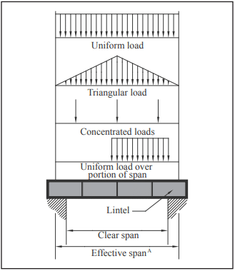
Arching Action

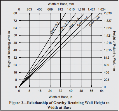
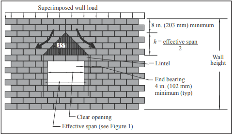
For some configurations, the masonry will distribute applied loads in such a manner that they do not act on the lintel. This is called arching action of masonry. Arching action can be assumed when the following conditions are met (see also Figure 2):

  • masonry wall laid in running bond,
  • sufficient wall height above the lintel to permit formation of a symmetrical triangle with base angles of 45° from the horizontal as shown in Figure 2,
  • at least 8 in. (203 mm) of wall height above the apex of the 45° triangle,
  • minimum end bearing (4 in. (102 mm) typ.) is maintained,
  • control joints are not located adjacent to the lintel, and
  • sufficient masonry on each side of the opening to resist lateral thrust from the arching action.

Lintel Loading

The loads supported by a lintel depend on whether or not arching action can occur. When arching is not present, the lintel self-weight, the full weight of the wall section above the lintel and superimposed loads are considered. Self weight is a uniform load based on lintel weight (see Table 1).

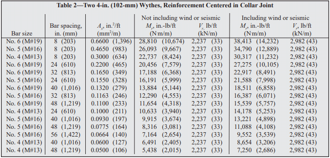
When arching occurs, the wall weight supported by the lintel is taken as the wall weight within the triangular area below the apex (see Figure 2 and Table 2). This triangular load has a base equal to the effective span length of the lintel and a height of half the effective span. Any superimposed roof and floor live and dead loads outside this triangle are neglected, since they are assumed to be distributed to the masonry on either side of the lintel. Loads applied within the triangle need to be considered, however.

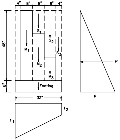
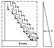
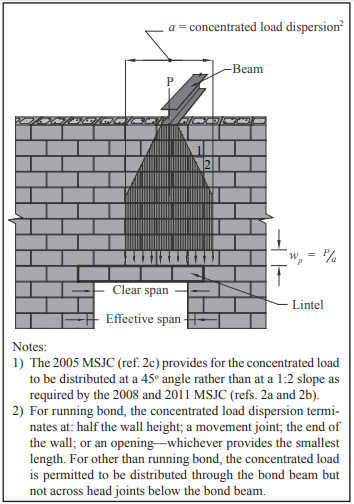
Concentrated loads are assumed to be distributed as illustrated in Figure 3. The load is then resolved onto the lintel as a uniform load, with a magnitude determined by dividing the concentrated load by this length. In most cases, this results in a uniform load acting over a portion of the lintel span.

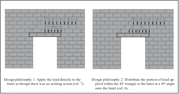
The MSJC (ref. 2) does not address how to apply uniform loads that are applied within the 45° triangle. There are two schools of thought (see Figure 4):

  1. Apply the full uniform load directly to the lintel without further distribution just as though there was no arching for those loads.
  2. Distribute the portions of uniform loads that are applied within the 45o triangle to the lintel. These uniform loads within the 45o triangle may be dispersed and distributed at a 45o angle onto the lintel (ref. 5).

Lintels are required to be designed to have adequate stiffness to limit deflections that would adversely affect strength or serviceability. In addition, the deflection of lintels supporting unreinforced masonry is limited to the clear lintel span divided by 600 to limit damage to the supported masonry (ref. 2).

DESIGN TABLES

Tables 3 and 4 present allowable shear and moment, respectively, for various concrete masonry lintels, with various amounts of reinforcement and bottom cover based on a specified compressive strength of masonry, f’m = 1,500 psi (10.3 MPa) and the allowable stress design provisions of the 2011 MSJC (ref. 2a) and the 2012 IBC (ref.1a).

DESIGN EXAMPLE

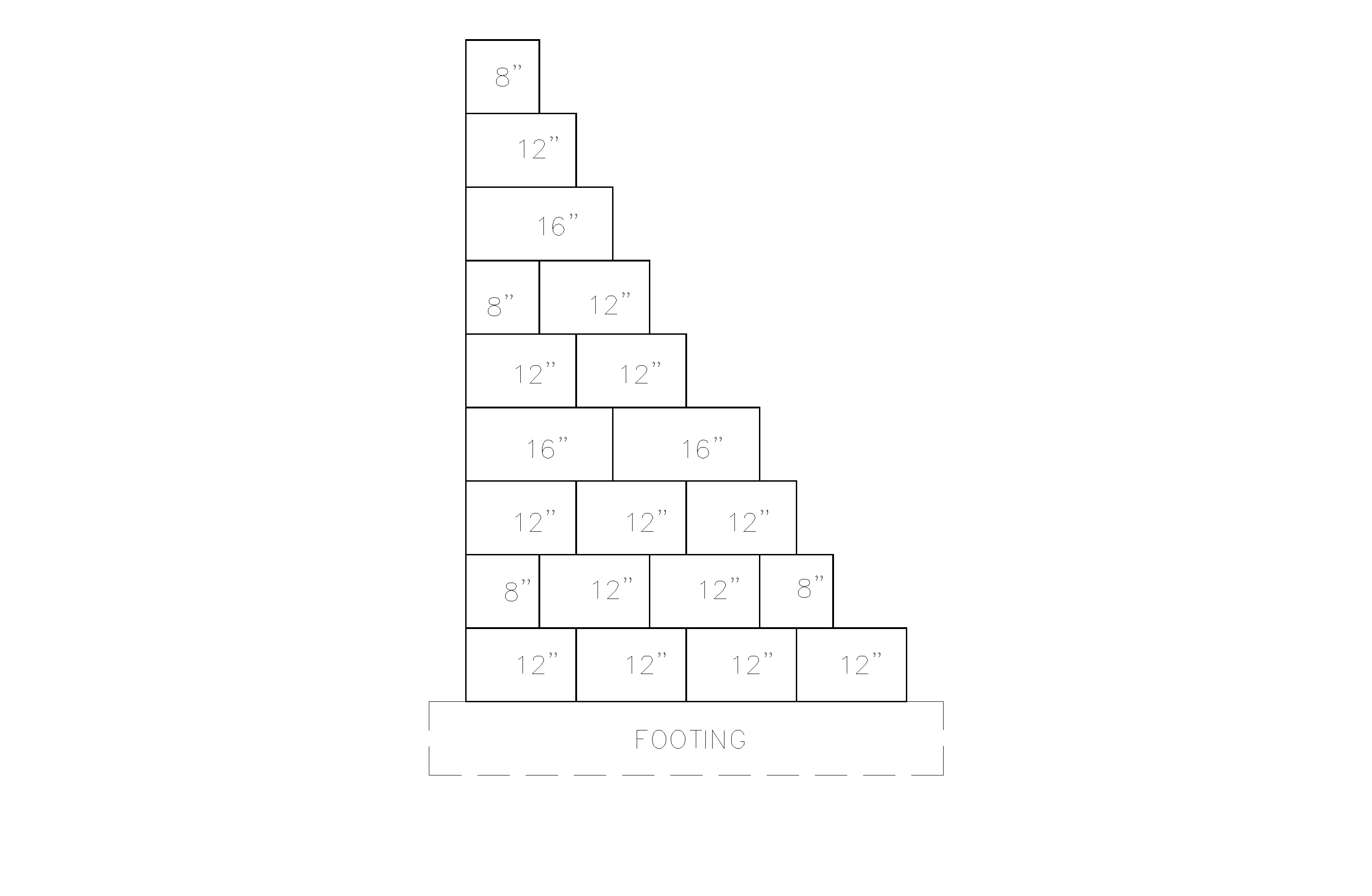
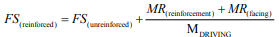
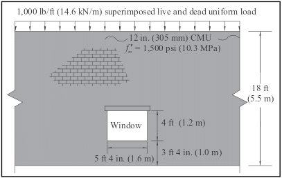
Design a lintel for a 12 in. (305 mm) normal weight concrete masonry wall laid in running bond with vertical reinforcement at 48 in. (1.2 m) o.c. The wall configuration is shown in Figure 5.

Case 1—Arching Action


Check for Arching Action
. Determine the height of masonry required for arching action. Assuming the lintel has at least 4 in. (102 mm) bearing on each end, the effective span is:

L = 5.33 + 0.33 = 5.67 ft (1.7 m).

The height of masonry above the lintel necessary for arching to occur in the wall (from Figure 2) is h + 8 in. (203 mm) = L/2 + 8 in. = 3.5 ft (1.1 m).
Based on an 8-in. (203-mm) high lintel, there is 18.0 – (3.33 + 4.0 + 0.67) = 10.0 ft (3.0 m) of masonry above the lintel. Therefore, arching is assumed and the superimposed uniform load is neglected.

Design Loads. Because arching occurs, only the lintel and wall dead weights are considered. Lintel weight, from Table 1, for 12 in. (305 mm) normal weight concrete masonry units assuming an 8 in. (203 mm) height is Dlintel = 88 lb/ft (1.3 kN/m).

For wall weight, only the triangular portion with a height of 3.5 ft (1.1 m) is considered. From Table 2, wall dead load is:

Dwall = 63 lb/ft² (3.5 ft)
= 221 lb/ft (3.2 kN/m) at the apex.

Maximum moment and shear are determined using simply supported beam relationships. The lintel dead weight is considered a uniform load, so the moment and shear are,

Mlintel = DlintelL²/8
= (88)(5.7)²/8
= 357 lb-ft (0.48 kN-m)
Vlintel = DlintelL/2
= (88)(5.7)/2 = 251 lb (1.1 kN)

For triangular wall load, moment and shear are,

Mwall = DwallL²/12
= (221)(5.7)²/12
= 598 lb-ft (0.81 kN-m)
Vwall = DwallL/4
= (221)(5.7)/4 = 315 lb (1.4 kN)

Because the maximum moments for the two loading conditions occur in the same locations on the lintel (as well as the maximum shears), the moments and shears are superimposed and summed:

Mmax = 357 + 598
= 955 lb-ft = 11,460 lb-in (1.3 kN-m)
Vmax = 251 + 315
= 566 lb (2.5 kN)

Lintel Design. From Tables 3 and 4, a 12 x 8 lintel with one No. 4 (M#13) bar and 3 in. (76 mm) or less bottom cover has adequate strength (Mall = 22,356 lb-in. (2.53 kN-m) and Vall = 2,152 lb (9.57 kN)). In this example, shear was conservatively computed at the end of the lintel. However, Building Code Requirements for Masonry Structures (ref. 2) allows maximum shear to be calculated using a distance d/2 from the face of the support.

Case 2—No Arching Action

Using the same example, recalculate assuming a 2 ft (0.6 m) height from the bottom of the lintel to the top of the wall. For ease of construction, the entire 2 ft (0.6 m) would be grouted solid, producing a 24 in. (610 mm) deep lintel.

Because the height of masonry above the lintel is less than 3.5 ft (1.1 m), arching cannot be assumed, and the superimposed load must be accounted for.

Dlintel = 264 lb/ft (3.9 kN/m), from Table 1. Because the lintel is 24 in. (610 mm) deep, there is no additional dead load due to masonry above the lintel.

Wtotal = 264 lb/ft + 1,000 lb/ft
= 1,264 lb/ft (18.4 kN/m)

Mmax = wL²/8
= (1,264)(5.7)²/8 x 12 in./ft
= 61,601 lb-in (7.0 kN-m)

Vmax = wL/2 = (1,264)(5.7)/2
= 3,602 lb (16.0 kN)

From Tables 3 and 4, a 12 x 24 lintel with one No. 4 (M#13) reinforcing bar and 3 in. (76 mm) or less bottom cover is adequate (Mall = 122,872 lb-in. (13.88 kN-m) and Vall = 10,256 lb (45.62 kN).

NOTATIONS

b           = width of lintel, in. (mm)
Dlintel   = lintel dead load, lb/ft (kN/m)
Dwall    = wall dead load, lb/ft (kN/m)
d           = distance from extreme compression fiber to centroid of tension reinforcement, in. (mm)
f’m         = specified compressive strength of masonry, psi (MPa)
h            = half of the effective lintel span, L/2, ft (m)
L            = effective lintel span, ft (m)
Mall       = allowable moment, in.-lb (N⋅m)
Mlintel   = maximum moment due to lintel dead load, in.-lb (N⋅m)
Mmax    = maximum moment, in.-lb (N⋅m)
Mwall    = maximum moment due to wall dead load moment, in.-lb (N⋅m)
Vall        = allowable shear, lb (N)
Vlintel    = maximum shear due to lintel dead load, lb (N)
Vmax     = maximum shear, lb (N)
Vwall     = maximum shear due to wall dead load, lb (N)
Wtotal   = total uniform live and dead load, lb/ft (kN/m)
w          = uniformly distributed load, lb/in. (N/mm)

REFERENCES

  1. International Building Code. International Code Council.
    1. 2012 Edition
  2. Building Code Requirements for Masonry Structures. Reported by the Masonry Standards Joint Committee. a. 2011 Edition: TMS 402-11/ACI 530-11/ASCE 5-11
  3. ASD of Concrete Masonry (2012 IBC & 2011 MSJC), TEK 14-07C, Concrete Masonry & Hardscapes Association, 2011.
  4. Weights and Section Properties of Concrete Masonry Assemblies, CMU-TEC-002-23, Concrete Masonry & Hardscapes Association, 2023.
  5. Openings in Concrete Masonry Walls (Part 1), Masonry Chronicles Winter 2008-09, Concrete Masonry Association of California and Nevada, 2009.

Design of Concrete Masonry Noncomposite (Cavity) Walls

INTRODUCTION

When selecting a building enclosure, concrete masonry cavity walls are considered to be one of the best solutions available for all types of buildings. From both an initial cost and life-cycle cost perspective, cavity wall construction is highly regarded as the prime choice in many applications.

Cavity walls typically consist of an inner wythe of concrete masonry units that are tied to an exterior wythe of architectural masonry units. The cavity space between the wythes is normally 2 to 4 ½ in. (51 to 114 mm) wide, easily accommodating rigid board insulation. The two wythes together provide a wall that is highly resistant to wind driven rain, absorbs and reflects sound, provides good thermal performance, and has excellent fire resistance characteristics.

Masonry walls constructed of two or more wythes can technically be classified in one of three ways, depending on how the wythes are designed and detailed. These wall types include composite, noncomposite and veneer assemblies. In noncomposite construction, covered in this TEK, each wythe is connected to the adjacent wythe with metal wall ties, but they are designed such that each wythe individually resists the loads imposed on it. Composite walls are designed so that the wythes act together as a single element to resist structural loads. This requires the masonry wythes to be connected by masonry headers or by a mortar- or grout-filled collar joint and wall ties (see ref. 4). In a veneer wall, the backup wythe is designed as the loadbearing system while the veneer provides a nonloadbearing architectural wall finish that transfers loads to the backup wythe through wall ties (see refs. 5, 6). Although Building Code Requirements for Masonry Structures (ref. 1) defines a cavity wall as a noncomposite masonry wall, the term cavity wall is also commonly used to describe a veneer wall with masonry backup.

This TEK illustrates the design of noncomposite concrete masonry walls based on Building Code Requirements for Masonry Structures (ref. 1), referred to here as the MSJC code. Each wythe of a noncomposite wall system can be designed to accommodate all types of loads, including gravity loads from roofs, walls and floors, as well as lateral loads from wind or earthquakes. The MSJC code design provisions are used to size these masonry walls.

STRUCTURAL DESIGN

The MSJC code includes noncomposite design provisions for both allowable stress design (Chapter 2) and empirical design (Chapter 5). The assumptions and relevant governing equations for each of these design approaches is given in references 2 and 3 respectively.

Concrete masonry cavity walls can be designed as either reinforced or unreinforced walls. For unreinforced design, flexural tensile stresses in masonry are resisted by bond developed between the masonry units and mortar; axial tension is not permitted (ref. 1). If direct axial tension is encountered in a design, reinforcement must be used. In reinforced masonry design, all tension is assumed to be resisted by reinforcement.

Empirical Design

Empirical design can be an expedient approach for typical loadbearing structures subjected to nominal wind loads (basic wind speed ≤ 110 mph, (177 km/h) (MSJC 5.1.2.2) and located in areas of low seismic risk, as it cannot be used for the design of seismic force resisting systems in SDC (Seismic Design Category) B or higher (MSJC 5.1.2.1). Empirical design utilizes prescriptive provisions, outlining criteria such as wall height to thickness ratios, minimum wall thickness and maximum building height.

References 1 and 3 contain maximum length-to-thickness or height-to-thickness ratios for empirically designed walls. When using these ratios for noncomposite multiwythe walls, the total wall thickness is taken as the sum of the nominal thicknesses of each wythe, neglecting the presence of any cavity thickness. Compressive stress is based on the gross cross-sectional area of all wythes, including hollow cells but not including the cavity between the wythes. When floor or roof loads are carried on only one wythe, only the gross cross-sectional area of that wythe is used to check the axial capacity. In addition, these walls must meet the following requirements for wall ties connecting the wythes:

  • wall ties of wire size W2.8 (3/16 in., MW 18), or metal wire of equivalent stiffness, spaced at a maximum of 24 in. (610 mm) o.c. vertically and 36 in. (914 mm) o.c. horizontally, with at least one wall tie for each 4½ ft² (0.42 m²) of wall area,
  • walls constructed with hollow units must use rectangular ties,
  • walls constructed with solid units must use Z-shaped ties with hooks at least 2 in. (51 mm) long,
  • wall ties may not have drips,
  • additional ties are required within 12 in. (305 mm) of all openings and must be spaced no more than 3 ft (914 mm) apart around the perimeter of the opening.

Requirements for bonding with joint reinforcement are the same as those for wall ties with the following exceptions: cross wire size may not be smaller than W1.7 (9 gage, MW 11) and the supported wall area per cross wire may not exceed 2 ft² (0.25 m²). In addition, the longitudinal wires must be embedded in mortar.

Allowable Stress Design

Similar to empirical design, MSJC allowable stress design includes prescriptive requirements for bonding wythes of noncomposite walls via wall ties, adjustable ties and joint reinforcement.

For rectangular ties, Z ties (for use with other than hollow units) and ladder or tab-type joint reinforcement, ties or cross wires of joint reinforcement, ties must be placed with a maximum spacing of 36 in. (914 mm) horizontally and 24 in. (610 mm) vertically. The minimum number of ties is one per:

  • 2 ft² (0.25 m²) of wall for wire size W 1.7 (9 gage, MW 11), and
  • 4½ ft² (0.42 m²) of wall for wire size W 2.8 (3/16 in., MW 18).

For adjustable ties, one tie must be provided for each 1.77 ft² (0.16 m²) of wall; maximum horizontal and vertical spacing is 16 in. (406 mm); misalignment of bed joints from one wythe to the other may not exceed 1 ¼ in. (31.8 mm); the maximum clearance between connecting parts of the tie is 1/16 in. (1.6 mm); and pintle ties must have at least two pintle legs of wire size W2.8 (3/16 in., MW 18) (see also Figure 1).

For noncomposite masonry walls, the following additional requirements apply.

  • Collar joints are not to contain headers, or be filled with mortar or grout.
  • Gravity loads from supported horizontal members are to be resisted by the wythe nearest the center of the span.
  • Bending moments about the weak axis of the wall and transverse loads are distributed to each wythe according to relative stiffness. This can be determined by:
    Wi = WT [EmIi/(EmIi+ EmI0)]
    Wo = WT [EmI0/(EmIi+ EmI0)]
  • Loads acting parallel to the wall are resisted by the wythe to which they are applied.
  • The cavity width between the wythes is limited to 4½ in. (114 mm) unless a detailed wall tie analysis is performed.

DESIGN EXAMPLES

The following examples illustrate the use of noncomposite masonry employing empirical and allowable stress design methods. Although there are no specific provisions in MSJC for noncomposite wall design using strength design, strength design could be used provided the same load distribution principles as presented for allowable stress design are employed.

Empirical Design Design Example:
Design the top story of a two-story noncomposite double wythe masonry wall system supported on continuous footings. Note that the design of the lower story, though not shown, is performed in the same manner, except that the floor live and dead loads from the upper story are also accounted for.

Given:

unsupported wall height= 10 ft (3.01 m)
superimposed gravity dead load= 220 plf (3.2 kN/m)
superimposed gravity live load= 460 plf (6.7 kN/m)
net superimposed uplift from wind= 120 plf (1.8 kN/m)
wind pressure= 24 psf (1,149 Pa)
eccentricity of all gravity loads= 0
f’m= 1,500 psi (10.3 MPa)
Em= 1,350 ksi (9,308 MPa)


Wall lateral support requirement: l/t or h/t < 18, so minimum required wall thickness = h/18
= 10 ft (12 in./ft)/18
= 6.7 in. (169 mm)

Try a 4-in. (102 mm) outer wythe and 6-in. (152 mm) inner wythe (providing a total nominal wall thickness of 10 in. (254 mm)), and check allowable axial compressive stress due to dead and live loads (gravity loads are carried by the inner wythe only):

dead:roof220 lb/ft
 wythe = 10 ft x 26 psf (ref. 8)260 lb/ft
live:roof460 lb/ft
total load: 940 lb/ft (13.7 kN/m)


Gross area of 6-in. (152-mm) wythe = 67.5 in.²/ft (ref. 7)
fa = 940 lb/ft/(67.5 in.²/ft) = 13.9 psi (0.096 MPa)
Fa = 75 psi (0.52 MPa) for Type M or S mortar, 70 psi (0.48 MPa) for Type N mortar (ref. 1)
fa < Fa (OK for all mortar types)

Per MSJC code section 5.8.3.1, the net uplift on the roof must be resisted by an anchorage system. Use a bond beam at the top of the inner wythe with vertical reinforcement to the foundation to provide this resistance.

ASD Reinforced Design Example:
Given:

unsupported wall height= 18 ft (5.5 m)
wind load, w= 36 psf (1,724 Pa)
net roof uplift at top of wall= 400 plf (5.8 kN/m) )
eccentricity of all vertical loads= 0
f’m= 1,500 psi (0.0718 MPa )
unit density= 115 pcf (1,842 kg/m³)
Grade 60 reinforcement 

Note: The 36 psf (1,724 Pa) wind load is much higher than is generally applicable when using empirical design.

Design the inside wythe first, as it must resist the uplift in addition to the flexural loads. Try two 6-in. (152 mm) wythes with No. 5 (M #16) reinforcement at 32 in. (813 mm) o.c.

Determine reinforcement needed for uplift at midheight:
uplift = 400 lb/ft – 34 lb/ft² (18 ft/2) = 94 lb/ft (1.37 kN/m) (ref. 8)
reinforcement needed = [(94 lb/ft)(32 in.)/(12 in./ft)]/[1.333(24,000 psi)] = 0.0078 in.²
As available for flexure = 0.31 – 0.0078 = 0.3022 in.²
Ms = FsAsjd = 1.333 (24,000 psi) (0.3022 in.²)(0.894)(2.813 in.)
= 24,313 lb-in. for 32 in. width
= 9,117 lb-in./ft (3,378 N⋅m/m) > 8,996 lb-in./ft (3,333 N⋅m/m), therefore Mm controls

Determine applied moment:
Since the wythes are identical, each would carry ½ the lateral load or ½ (36 psf) = 18 psf (124 kPa)
Mmax = wl²/8 = (18 psf)(18 ft)²(12 in./ft)/8
= 8,748 lb-in./ft (3,241 N⋅m/m) < 8,996 lb-in./ft (3,333 N⋅m/m) OK

Check shear:
Vmax = wl/2 = (18psf)(18 ft)/2 = 162 lb/ft (2.36 kN/m)
fv = Vmax/bd = 162 lb/ft/(12 in.)(2.813 in.) = 4.80 psi (33 kPa)
Fv = 37 x 1.333 = 51 psi (351 kPa)
4.80 psi (33 kPa) < 51 psi (351 kPa) OK

A quick check of the outside wythe shows that the same reinforcement schedule will work for it as well. Therefore, use two 6-in. (152-mm) wythes with No. 5 (M #16) vertical reinforcement at 32 in. (813 mm) o.c.

This wall could be designed using an unreinforced 4-in. (102 mm) outside wythe and a reinforced 8-in. (203-mm) inside wythe, with lateral loads distributed to each wythe according to the uncracked stiffness per MSJC section 1.9.2. Experience has shown, however, that the design would be severely limited by the capacity of the unreinforced outside wythe. Additionally, such a design could be used only in SDC A or B since 4-in. (102 mm) concrete masonry does not have cores large enough to reinforce.

Another alternative would be to design this system treating the 4 in. (102 mm) outer wythe as a nonloadbearing veneer. Designing this wall as a 4-in. (102 mm) veneer with an 8-in. (203 mm) reinforced structural backup wythe would result in No. 5 bars at 16 in. (M #16 at 406 mm) on center. This is the same amount of reinforcement used in the example above (two 6-in. (152 mm) wythes with No. 5 (M #16) at 32 in. (813 mm) on center). However, because the 6-in. (152 mm) units have smaller cores, 30% less grout is required.

The design using two 6-in. (152-mm) reinforced wythes has the following advantages over veneer with structural backup:

  • no limitation on SDC as when a veneer or an unreinforced outer wythe is used,
  • no limitation on wind speed as with a veneer,
  • equal mass on both sides of the wall permitting the use of the prescriptive energy tables for integral insulation, and
  • the flexibility of using units with different architectural finishes on each side.

NOMENCLATURE

As          = effective cross-sectional area of reinforcement, in.²(mm²)
b            = width of section, in. (mm)
d            = distance from extreme compression fiber to centroid of tension reinforcement, in. (mm)
Em         = modulus of elasticity of masonry, psi (MPa)
Es          = modulus of elasticity of steel, psi (MPa)
Fa          = allowable compressive stress due to axial load only, psi (kPa)
Fb          = allowable compressive stress due to flexure only, psi (kPa)
Fs          = allowable tensile or compressive stress in reinforcement, psi (kPa)
Fv          = allowable shear stress in masonry, psi (MPa)
fa           = calculated compressive stress in masonry due to axial load only, psi (kPa)
f’m         = specified compressive strength of masonry, psi (kPa)
h            = effective height, in. (mm)
fv           = calculated shear stress in masonry, psi (MPa)
Ii            = average moment of inertia of inner wythe, in.4/ft (m4/m)
Io           = average moment of inertia of outer wythe, in.4/ft (m4/m)
j             = ratio of distance between centroid of flexural compressive forces and centroid of tensile forces to depth d
k           = ratio of distance between compression face of wall and neutral axis to depth d
l            = clear span between supports, in. (mm)
M          = moment at the section under consideration, in.-lb/ft (N⋅m/m)
Mm       = flexural capacity (resisting moment) when masonry controls, in.-lb/ft (N⋅m/m)
Mmax   = maximum moment at the section under consideration, in.-lb/ft (N⋅m/m)
Ms        = flexural capacity (resisting moment) when reinforcement controls, in.-lb/ft (N⋅m/m)
t            = nominal thickness of a member, in. (mm)
Vmax    = maximum shear at the section under consideration, lb/ft (kN/m)
Wi        = percentage of transverse load on inner wythe
Wo       = percentage of transverse load on outer wythe
WT       = total transverse load
w         = wind pressure, psf (Pa)
ρ          = reinforcement ratio

REFERENCES

  1. Building Code Requirements for Masonry Structures, ACI 530-02/ASCE 5-02/TMS 402-02. Reported by the Masonry Standards Joint Committee, 2002.
  2. ASD of Concrete Masonry (2012 IBC & 2011 MSJC), TEK 14-07C, Concrete Masonry & Hardscapes Association, 2004.
  3. Empirical Design of Concrete Masonry Walls, TEK 1408B, Concrete Masonry & Hardscapes Association, 2003
  4. Structural Design of Unreinforced Composite Masonry, TEK 16-02B, Concrete Masonry & Hardscapes Association, 2001.
  5. Concrete Masonry Veneers, TEK 03-06C, Concrete Masonry & Hardscapes Association, 2012.
  6. Reinforced Composite Concrete Masonry Walls, TEK 1603B, Concrete Masonry & Hardscapes Association, 2006.
  7. Weights and Section Properties of Concrete Masonry Assemblies, CMU-TEC-002-23, Concrete Masonry & Hardscapes Association, 2023.


Reinforced Composite Concrete Masonry Walls

INTRODUCTION

Reinforced composite concrete masonry walls can provide geometric diversity. Composite walls consist of multiple wythes of masonry connected such that they act as a single structural member. There are prescriptive requirements in both the International Building Code (ref. 1) and Building Code Requirements for Masonry Structures (ref. 2) for connecting the wythes. General information on composite walls is included in TEK 16-01A, Multi-Wythe Concrete Masonry Walls (ref. 3) which is intended to be used in conjunction with this TEK.

Reinforced composite masonry walls are designed by the same procedures as all reinforced masonry walls. They must meet the same construction requirements for reinforcing placement, tolerances, grout placement, and workmanship as all reinforced concrete masonry walls.

Although composite walls can be reinforced or unreinforced, this TEK discusses the requirements for reinforced composite walls. Unreinforced composite walls are discussed in TEK 1602B, Structural Design of Unreinforced Composite Masonry (ref. 4).

DESIGN CONSIDERATIONS

Composite masonry is defined as “multicomponent masonry members acting with composite action” (ref. 2). For a multiwythe wall section to act compositely, the wythes of masonry must be adequately connected. Provisions for properly bonding the wythes are discussed in TEK 16-01A. When wall ties are used, the collar joint – the vertical space between the two wythes of masonry – must be filled solid with grout or mortar (refs. 1, 2). However, when reinforcement is placed in the collar joint, grout must be used to fill the collar joint.

Considerations When Choosing a Cross Section

Unlike single wythe walls, where the geometric cross section is set by the product as manufactured, the cross section of a composite wall is determined by the combination of units and collar joint which can theoretically be any thickness. Practically speaking, code, structural and architectural requirements will narrow the options for wall sections. In addition to structural capacity, criteria specific to cross-section selection for reinforced composite walls include:

• location of reinforcement in collar joint or in unit cores;

• collar joint thickness;

• unit selection for each wythe.

Structural Reinforcement Location

The engineer has the option of locating the structural reinforcing steel in the collar joint or in one or both wythes. While there is no direct prohibition against placing reinforcement in both the collar joint and the unit cores, practically speaking there is rarely a structural reason to complicate the cross section with this configuration.

With some units, it may be easier to install reinforcement in the collar joint, such as when both wythes are solid or lack sufficient cell space for reinforcing bars. Depending on the units selected, the collar joint may or may not provide the option to center the reinforcement within the wall cross section. For example, when the units are not the same thickness, the collar joint does not necessarily span the center of the section.

Conversely, if off-set reinforcing is preferred, perhaps to accommodate unbalanced lateral loads, it may be benefi cial to place the vertical bars in the unit cores. Placing reinforcement in the unit cores permits a thinner collar joint and possibly a thinner overall cross-section. Unit cores may provide a larger and less congested opening for the reinforcing bars and grout since the collar joint will be crossed with connecting wall ties. There is also the possibly that for a given geometry, centered reinforcement does end up in a core space.

Reinforcement can also be placed in the cells of each wythe, providing a double curtain of steel to resist lateral loads from both directions, as in the case of wind pressure and suction.

Collar Joint Width

There are no prescriptive minimums or maximums explicit to collar joint thickness in either Building Code Requirements for Masonry Structures or the International Building Code, however there are some practical limitations for constructability and also code compliance in reinforcing and grouting that effect the collar joint dimension. Many of these are covered in TEK 16-01A but a few key points from the codes that are especially relevant for reinforced composite masonry walls included below:

  • Wall tie length: Noncomposite cavity walls have a cavity thickness limit of 4½ in. (114 mm) unless a wall tie analysis is performed. There is no such limitation on width for filled collar joints in composite construction since the wall ties can be considered fully supported by the mortar or grout, thus eliminating concern about local buckling of the ties. Practically speaking, since cavity wall construction is much more prevalent, the availability of standard ties may dictate collar joint thickness maximums close to 4½ in. (114 mm).
  • Pour and lift height: Since the collar joint must be fi lled, the width of the joint infl uences the lift height. Narrow collar joints may lead to low lift or pour heights which could impact cost and construction schedule. See Table 1 in TEK 03-02A, Grouting Concrete Masonry Walls (ref. 5) for more detailed information.
  • Course or fine grout: Codes require a minimum clear distance of ¼-in. (6.3-mm) for fine grout and ½-in. (13-mm) for coarse grout between reinforcing bars and any face of the masonry unit.
  • Course or fine grout: Codes require a minimum clear distance of ¼-in. (6.3-mm) for fine grout and ½-in. (13-mm) for coarse grout between reinforcing bars and any face of the masonry unit.
  • Grout or mortar fill: Although codes permit collar joints to be filled with either mortar or grout, grout is preferred because it helps ensure complete filling of the collar joint without creating voids. Note that collar joints less than ¾ in. (19 mm), unless otherwise required, are to be filled with mortar as the wall is built. Increasing the slump of the mortar to achieve a solidly filled joint is preferred. This effectively requires a ¾-in. (19-mm) minimum on collar joints with structural reinforcing since it is also a code requirement that reinforcing bars be placed in grout, not mortar.
  • Reinforcing bar diameter: The reinforcing bar diameter cannot exceed one-half the least clear dimension of the collar joint.
  • Horizontal bond beams: Bond beams may be required to meet prescriptive code requirements such as seismic detailing. The collar joint then must be wide enough to accommodate the horizontal and vertical reinforcement along with the accompanying clearances for embedment in grout.  

Unit Selection for Each Wythe

Aesthetic criteria may play a primary role in unit selection for reinforced composite walls. Designing the composite wall to match modular dimensions may make detailing of interfaces much easier. Window and door frames, foundations, connectors and other accessories may coordinate better if typical masonry wall thicknesses are maintained. Additional criteria that influence the selection of units for reinforced composite walls include:

  • Size and number of reinforcing bars to be used and the cell space required to accommodate them.
  • Cover requirements (see ref. 6) may come into play when reinforcement is placed in the cells off-center. Cover requirements could affect unit selection, based on the desired bar placement; face shell thickness and cell dimensions.
  • If double curtains of vertical reinforcement are used, it is preferable to use units of the same thickness to produce a symmetrical cross section.

Structural Considerations

Some structural considerations were addressed earlier in this TEK during the discussion of cross section determination. Since reinforced composite masonry by definition acts as one wall to resist loads, the design procedures are virtually the same as for all reinforced masonry walls. TEK 14-07C, ASD of Concrete Masonry (2012 IBC & 2011 MSJC) (ref. 7) details design procedures. A few key points should be stressed, however:

  • Analysis: Empirical design methods are not permitted to be used for reinforced multiwythe composite masonry walls.
  • Section properties: Section properties must be calculated using the transformed section method described in TEK 1601A (ref. 3).
  • Shear stresses: Shear stress in the plane of interface between wythes and collar joint is limited to 5 psi (34.5 kPa) for mortared collar joints and 10 psi (68.9 kPa) for grouted collar joints.

DESIGN TABLES

Design tables for select reinforced composite walls are included below. The tables include maximum bending moments and shear loads that can be sustained without exceeding the allowable stresses defined in the International Building Code and Building Code Requirements for Masonry Structures. These can be compared to Tables 1 and 2 of TEK 14-19B, ASD Tables for Reinforced CM Walls (2012 IBC & 2011 MSJC) (ref. 8) for wall subjected to uniform lateral loads to ensure the wall under consideration is not loaded beyond its design capacity. The examples are based on the following criteria:

The examples are based on the following criteria:

• Allowable stresses:

In addition to these tables, it is important to check all code requirements governing grout space dimensions and maximum reinforcement size to ensure that the selected reinforcing bar is not too large for the collar joint. The designer must also check shear stress at the unit/grout interface to ensure it does not exceed the code allowable stress for the design loading.

CONSTRUCTION AND DETAILING REQUIREMENTS

With composite wall construction, the two masonry wythes are not required to be built at the same time unless the collar joint is less than ¾ in. (19 mm), as the code mandates that those collar joints be mortared as the wall is built. Practically speaking it is easier to build both wythes at the same time to facilitate placing either the grout or the mortar in the collar joint at the code required pour heights.

It can be more complex to grout composite walls. Consider that a composite wall may have requirements to grout the collar joint for the full wall height and length but the cores of the concrete masonry units may only need to be partially grouted at reinforcing bar locations. Installing reinforcement and grout in the collar joint space can also be more time-consuming because of congestion due to the wall ties.

Nonmodular composite wall sections may cause diffi culty at points where they interface with modular elements such as window and door frames, bonding at corners and bonding with modular masonry walls. 

NOTATIONS

As     = effective cross-sectional area of reinforcement, in.²/ft (mm²/m)
d       = distance from extreme compression fiber to centroid of tension reinforcement, in. (mm)
Eg     = modulus of elasticity of grout, psi (MPa)
Em    = modulus of elasticity of masonry in compression, psi (MPa)
Es     = modulus of elasticity of steel, psi (MPa)
Fb     = allowable compressive stress due to flexure only, psi (MPa)
Fs     = allowable tensile or compressive stress in reinforcement, psi (MPa)
Fv     = allowable shear stress in masonry, psi (MPa)
f’g     = specified compressive strength of grout, psi (MPa)
f’m    = specified compressive strength of masonry, psi (MPa)
Mr    = resisting moment of wall, in.-lb/ft (kNm/m)
Vr     = resisting shear of wall, lb/ft (kN/m)

REFERENCES

  1. International Building Code 2003. International Code Council, 2003.
  2. Building Code Requirements for Masonry Structures, ACI 530-05/ASCE 5-05/TMS 402-05. Reported by the Masonry Standards Joint Committee, 2005.
  3. Multi-Wythe Concrete Masonry Walls, TEK 16-01A. Concrete Masonry & Hardscapes Association, 2005.
  4. Structural Design of Unreinforced Composite Masonry, TEK 16-02B, Concrete Masonry & Hardscapes Association, 2001
  5. Grouting Concrete Masonry Walls, TEK 03-02A, Concrete Masonry & Hardscapes Association, 2005.
  6. Steel Reinforcement for Concrete Masonry, TEK 12-04D, Concrete Masonry & Hardscapes Association, 2006.
  7. ASD of Concrete Masonry (2012 IBC & 2011 MSJC), TEK 14-07C, Concrete Masonry & Hardscapes Association, 2004.
  8. ASD Tables for Reinforced CM Walls (2012 IBC & 2011 MSJC), TEK 14-19B, Concrete Masonry & Hardscapes Association, 2011.

Multi-Wythe Concrete Masonry Walls

INTRODUCTION

Multiwythe masonry walls can take one of several forms: composite, noncomposite or veneer walls. The primary differences between these wall systems are in construction details and how applied loads are assumed to be carried and distributed through the loadbearing system.

In composite masonry, multiwythe masonry members act with composite action (refs. 1, 2). That is, composite walls are designed so that the wythes act together as a single structural member to resist loads. This requires that the masonry wythes be connected by masonry headers (which are rarely used due to cost and detailing restrictions) or by a mortar- or grout-filled collar joint and wall ties to help ensure adequate load transfer between wythes.

In contrast, each wythe of a noncomposite masonry wall (also referred to as a cavity wall) is connected to the adjacent wythe with metal wall ties, but they are designed such that each wythe individually resists the loads imposed on it. Transverse bending moments (flexure), such as those due to wind, are distributed to each wythe in proportion to its relative stiffness. Loads acting parallel to the plane of a noncomposite wall (in-plane) are resisted only by the wythe on which the loads are applied, neglecting stress transfer between wythes.

In a veneer wall, the backup wythe is designed as the loadresisting system, with the veneer providing the architectural wall finish. The anchored veneer transfers all out-of-plane loads to the backup through wall ties, while supporting its own weight inplane. Veneer walls are not covered in this TEK. Architectural detailing is covered in Concrete Masonry Veneer Details, TEK 0510B (ref. 3). Prescriptive design and detailing requirements are included in Concrete Masonry Veneers, TEK 03-06C, and (ref. 4), while engineered design procedures are outlined in Structural Design of Unreinforced Composite Masonry, TEK 16-02B (ref. 5). Note that although Building Code Requirements for Masonry Structures defines a cavity wall as a noncomposite masonry wall, the term cavity wall is also commonly used to describe a veneer wall with masonry backup.

Although Building Code Requirements for Masonry Structures includes design provisions for noncomposite and composite masonry walls, these design approaches are rarely taken with masonry walls, as they require two structural walls to be constructed adjacent to one another. In other words, if the structural design dictates the use of a 12-in. (305-mm) thick wall, it is often easier and more cost effective to use a single 12-in. (305-mm) wythe rather than a composite system consisting of 4-in. and 8-in. (102- and 203-mm) units. The primary advantage of using composite and noncomposite construction is in applications where different architectural features are desired on each side of a fully exposed concrete masonry wall. Greater flexibility in moisture control and insulation, as well as increased fire resistance rating and sound transmission class, can also be realized when compared to single wythe walls.

Information on the allowable stress design method, the strength design method and empirical design can be found in references 6, 7 and 8, respectively. The criteria specific to noncomposite and composite masonry walls are discussed in this TEK. Design tables are included in Design of Concrete Masonry Noncomposite Walls, TEK 16-04A, and Structural Design of Unreinforced Composite Masonry, TEK 16-02B (refs. 9, 10).

NONCOMPOSITE WALLS

In noncomposite construction, the wythes are connected by wall ties, as opposed to being rigidly bonded as in composite walls. The joint between wythes of noncomposite walls are not permitted to contain headers, grout or mortar.

With the exception of structural load paths and wall tie spacing requirements, architectural details for noncomposite masonry walls are nearly indistinguishable from those for masonry veneer on masonry backup. See Concrete Masonry Veneer Details, TEK 05-01B and Concrete Masonry Veneers, TEK 03-06C (refs. 3, 4).

Structural Design

Noncomposite walls are designed as follows: imposed vertical loads are carried by the wythe closest to the center of span of the supported member; bending moments are distributed to each wythe in proportion to its relative stiffness; and loads acting parallel to the plane of the wall (shear loads) are carried only by the wythe affected. In addition, the cavity width is limited to 4 ½ in. (114 mm) unless a detailed wall tie analysis is performed.

Transverse (out-of-plane) loads are distributed based on the wythe flexural stiffness as indicated by the moment of inertia, as follows:

Building Code Requirements for Masonry Structures includes prescriptive wall tie spacing requirements to aid compatible lateral deflection between wythes (see Figure 1). Wire wall ties, which may also include cross wires of horizontal joint reinforcement, are used to connect the wythes. Unless a detailed analysis is performed, the prescriptive requirements apply. In addition to the provisions shown in Figure 1, these prescriptive requirements include:

  • Collar joints may not contain headers, grout, or mortar.
  • Where the cross wires of joint reinforcement are used as ties, the joint reinforcement is required to be ladder-type or tab-type, as the truss-type restricts differential in-plane movement between the two wythes. Adjustable joint reinforcement assemblies are also permitted, and are considered to be a type of adjustable tie.
  • Additional requirements for wall ties can be found in Anchors and Ties for Masonry, TEK 12-01B (ref. 11).

COMPOSITE WALLS

Composite walls are multiwythe walls where both wythes act structurally as one unit. They depend on sufficient stress transfer across the joint between wythes for composite action. In addition to the general design requirements to ensure sufficient structural capacity that are applicable to all structural masonry walls, Building Code Requirements for Masonry Structures contains prescriptive requirements for bonding the wythes of composite walls as well as allowable shear stresses for the collar joint. While not prohibited by the code (ref. 2), wythes of composite masonry walls should not be constructed with dissimilar materials, such as clay and concrete masonry, as rigidly bonding such materials together does not permit differential movement between wythes.

Composite walls are most often designed with the axial load from floor slabs or the roof carried by the inner wythe of masonry. The vertical joint between wythes may contain either vertical or horizontal reinforcement, or reinforcement may be placed in either wythe. The thickness of the joint between adjacent wythes is not limited in thickness but is typically sized to accommodate modular layout and any reinforcement that may be placed in the joint. Stresses in each wythe due to axial load and flexure are calculated using the modular ratio, n, to transform sections using elastic analysis and assuming no slip at the collar joint, as shown in the following example.

Example: Reinforced Composite Wall Transformed Section and Neutral Axis

Consider a composite masonry wall constructed of 6-in. (152-mm) concrete masonry, a 2-in. (51-mm) grouted collar joint containing vertical No. 4 (M#13) bars at 48 in. (1,219 mm) on center, and 4-in. (102-mm) concrete brick. Moduli of elasticity for the materials are:

concrete masonry:
Em = 900 f’m = 900(1,500 psi)
= 1,350,000 psi (9,310 MPa)

grout:
Eg = 500fg = 500(2,000 psi)
= 1,000,000 psi (6,890 MPa)

steel:
Es = 29,000,000 psi (200 GPa)

The modular ratio, n, for grout and steel are:

ng = Eg/Em = 1,000,000/1,350,000 = 0.74
ns = Es/Em = 29,000,000/1,350,000 = 21.5

Using these modular ratios, equivalent areas of grout and steel based on a 12-in. (305-mm) width of concrete masonry are:

ng Ag = 0.74 (2 in. x 12 in.) = 17.8 in.² (11,480 mm²)
ns As = 21.5 (0.20 in.²/bar x 0.25 bar/ft) = 1.08 in.² (697 mm²)

The resulting transformed section is shown in Figure 2.

The net cross-sectional areas of the 6-in. (152-mm) and 4-in. (102-mm) concrete masonry wythes are 24.0 in.²/ft (0.051 m²/m) and 43.5 in.c/ft (0.092 m²/m), respectively (ref. 12). Determine the total transformed area, Atr:

Atr = 24 + 17.8 + 1.08 + 43.5 in.²/ft
= 86.4 in.²/ft (0.18 m²/m)

Next, determine the neutral axis location of the transformed section, by calculating , the distance from the neutral axis of the 6-in. (152-mm) concrete masonry to the neutral axis of the transformed section.

Moments of inertia of the three wall elements are:
(Icm) = 130.0 in.4/ft (1.78 x 108 mm4/m) (ref. 12)
Ig = (1/12) bh³ = (1/12)(8.9)(2)³ = 5.9 in.4/ft (8.10 x 107 mm4/m)
Is = (1/12) bh³ = (1/12)(2.2)(0.5)³ = 0.023 in.4/ft (3.13 x 104 mm4/m)
(Icm)4-in. = 47.6 in.4/ft (6.50 x 107 mm4/m) (ref. 12)

Using the parallel axis theorem, the moment of inertia of the transformed section, Itr, is:

Stresses in each element are then determined using: the transformed moment of inertia, Itr: the modular ratio, n; the area of the transformed section, Atr; and the distance from the extreme fiber to the neutral axis of the composite section, c. For example, the calculated tension in the steel due to flexure is:

Bonding the Wythes

To ensure shear transfer, Building Code Requirements for Masonry Structures requires that the joint between wythes either be filled with mortar or grout and connected by wall ties or be crossed by connecting masonry headers.

Wall tie spacing requirements are illustrated in Figure 3.

Although allowed, the use of masonry headers is an outdated method of connecting masonry wythes and is not recommended for several reasons. Headers are less ductile than metal wall ties, making accommodation for differential movement a critical issue. Differential movement can shear the headers, effectively eliminating the composite action, particularly with the combination of concrete masonry and clay masonry wythes. Also, walls bonded by headers are also more susceptible to water penetration.

When headers are used, they must be uniformly spaced and have a total cross-sectional area not less than four percent of the total wall surface area. Headers are also required to be embedded at least 3 in. (76 mm) into each wythe. See Figure 3.

Construction Considerations

In composite masonry construction, insulation and vapor retarders, if required, can not be located in the joint between wythes, as is commonly done in noncomposite construction. Insulation can be located either in the cores of the inner wythe or on the wall interior.

Because the two wythes of a composite wall act as one structural unit, vertical movement joints, including fire-rated control joints, should extend through both wythes at the same location across the cavity joint.

NOTATIONS

An   = net cross-sectional area of a wall element, in.²/ft (mm²/m)
Atr  = area of the transformed section, in.²/ft (mm²/m)
c     = the distance from the extreme fiber to the neutral axis of the composite section, in. (mm)
d     = distance from extreme compression fiber to centroid of tension reinforcement, in. (mm)
Eg    = modulus of elasticity of grout, psi (MPa)
Em   = modulus of elasticity of masonry in compression, psi (MPa)
Es    = modulus of elasticity of steel, psi (MPa)
f’g    = specified compressive strength of grout, psi (MPa)
f’m    = specified compressive strength of masonry, psi (MPa)
fs      = calculated tensile or compressive stress in reinforcement, psi (MPa)
Icm   = moment of inertia of concrete masonry, in.4/ft (mm4/m)
Ig     = moment of inertia of the grout, in.4/ft (mm4/m)
Is      = moment of inertia of the steel, in.4/ft (mm4/m)
Ii       = average moment of inertia of inner wythe, in.4/ft (mm4/m)
Io      = average moment of inertia of outer wythe, in.4/ft (mm4/m)
Itr     = moment of inertia of transformed section, in.4/ft (mm4/m)
M     = maximum moment at the section under consideration, in-lb/ft (N-mm/m)
n       = modular ratio
Wi     = transverse load on inner wythe, psf (kPa)
Wo     = transverse load on outer wythe, psf (kPa)
wT     = total transverse load, psf (kPa)
        = distance from the neutral axis of an element to the neutral axis of the transformed section, in. (mm)

REFERENCES

  1. International Building Code, 2003, With Commentary. International Code Council, Inc., 2004.
  2. Building Code Requirements for Masonry Structures, ACI 530-05/ASCE 5-05/TMS 402-05. Reported by the Masonry Standards Joint Committee, 2005.
  3. Concrete Masonry Veneer Details, TEK 05-1B, Concrete Masonry & Hardscapes Association, 2003.
  4. Concrete Masonry Veneers, TEK 03-06C, Concrete Masonry & Hardscapes Association, 2012.
  5. Structural Design of Unreinforced Composite Masonry, TEK 16-02B, Concrete Masonry & Hardscapes Association, 2001.
  6. ASD of Concrete Masonry (2012 IBC & 2011 MSJC), TEK 14-7C, Concrete Masonry & Hardscapes Association, 2004.
  7. Strength Design Provisions for Concrete Masonry, TEK 14-04B, Concrete Masonry & Hardscapes Association, 2008.
  8. Empirical Design of Concrete Masonry Walls, TEK 1408B, Concrete Masonry & Hardscapes Association, 2008.
  9. Design of Concrete Masonry Noncomposite Walls, TEK 16-04A, Concrete Masonry & Hardscapes Association, 2004.
  10. Structural Design of Unreinforced Composite Masonry TEK 16-02B, Concrete Masonry & Hardscapes Association, 2001.
  11. Anchors and Ties for Masonry, TEK 12-01B, Concrete Masonry & Hardscapes Association, 2011.
  12. Weights and Section Properties of Concrete Masonry Assemblies, CMU-TEC-002-23, Concrete Masonry & Hardscapes Association, 2023.

Seismic Design of Segmental Retaining Walls

INTRODUCTION

This TECH describes a method of analysis and design for conventional and geosynthetic-reinforced segmental retaining walls (SRWs) under seismic loading. The methodology extends the approach for structures under static loading to simple structures that may be required to resist additional dynamic loads due to earthquakes. The seismic design method described briefly in this Tech Note, and in detail in the CMHA Design Manual for Segmental Retaining Walls and SRWallv4 design software (refs. 1, 2), adopts a pseudo-static approach and uses the Mononobe-Okabe (M-O) method to calculate dynamic earth forces. The methodology adopts many of the recommendations contained in AASHTO/FHWA (refs. 3, 4) guidelines for the design and analysis of mechanically stabilized earth (MSE) structures subjected to earthquake loads. However, the CMHA Design Manual for Segmental Retaining Walls goes beyond the AASHTO/FHWA publications by addressing the unique stability requirements of SRWs that are constructed with a dry-stacked column of modular block units.

Properly designed reinforced SRWs subjected to seismic and/or dynamic loading will in general perform well due to their flexible nature and enhanced ductility. When an SRW requires seismic analysis, that evaluation should be performed in addition to the static analysis to satisfy all static and seismic safety factors, as outlined in the Design Manual for Segmental Retaining Walls. The project’s geotechnical engineer should select the ground acceleration design parameters considering the local experience, state of practice and site conditions. CMHA’s methodology uses a displacement approach that explicitly incorporates wall movement in the stability analysis, assuming small outward displacements are allowed, and reduces the Peak Ground Acceleration (PGA) following FHWA’s approach. It should be noted that outward displacements caused by “near” maximum probable magnitude earthquakes may bring SRWs outside of tolerable batter deviations, thereby requiring mitigation. As with any other structure, the intent of the seismic design is to prevent catastrophic failure (a failure leading to risk to life, limb, or property), and needs to be evaluated after a near design event.

For satisfactory performance in the field, the designer should specify the best construction and inspection practices, adequately addressing items such as materials, installation, compaction, and internal and external drainage (i.e., drain tiles, chimney drains, swales, etc.). For more details refer to SRW-TEC-005-09, Guide to Segmental Retaining Walls (ref. 5), SRW-TEC-008-12, Inspection Guide for Segmental Retaining Walls (ref. 6), and the CMHA Design Manual for Segmental Retaining Walls.

DESIGN ASSUMPTIONS

The CMHA seismic design and analysis methodology applies when the following conditions are met:

  • SRW structures are free-standing and able to displace horizontally at the base and yield laterally through the height of the wall. This assumption is based on installation recommendations of a system that is placed on soils and a flexible leveling pad of well-compacted gravel or unreinforced weak concrete that can crack if necessary.
  • Reinforced and retained soils are cohesionless, unsaturated, and homogeneous. Soil strength is described by the Mohr-Coulomb failure criterion. The apparent cohesive strength component reported under Mohr-Coulomb failure criterion is ignored for conservatism. Adequate drainage details should also accompany the design to ensure the soils remain unsaturated and that the assumed design conditions are reached and maintained.
  • Vertical ground acceleration is zero (kv = 0). Vertical ground acceleration is ignored based on the presumption that horizontal and vertical accelerations associated with a seismic event do not coincide.
  • Geometry is limited to infinite or broken-backslope, and constant horizontal foreslope angle.
  • Live surcharges are ignored at the top of the soil surface behind the facing column given their transient nature.
  • Retained and reinforced soils are placed to a depth corresponding to the full height of the SRW facing units (i.e. wall design height, H).
  • Cap units are ignored in the stability analysis and assumed to be securely attached such that they cannot be dislodged during ground shaking.
  • The stabilizing influence of the wall embedment is ignored with the exception of bearing capacity analyses.
  • No permanent surcharge or footing load exists within the active failure wedge.
  • Global stability involving failure of soil volumes beyond the base of the SRW unit column and/or geosynthetic reinforced fill zone is not considered.
  • SRW structures are built on competent foundations for which excessive settlement, squeezing or liquefaction are not potential sources of instability.

If there are more complex conditions, or for cases where M-O formulation leads to unrealistic results, it is recommended that numerical procedures using the same principles of M-O formulation be used. These include the well-known graphical Culmann method, Coulomb’s trial wedge method, or limit equilibrium slope stability programs that are outside of the scope of the CMHA Design Manual.

A limitation of the pseudo-static seismic design method presented here is that it can only provide an estimate of the margins of safety against SRW collapse or component failure, and does not provide any direct estimate of anticipated wall deformations. This is a limitation common to all limit-equilibrium design methods in geotechnical engineering.

GEOSYNTHETIC REINFORCED SEGMENTAL RETAINING WALLS— MODES OF FAILURE

Stability analyses for geosynthetic reinforced SRW systems under static and seismic loading conditions involve separate calculations to establish factors of safety against external, internal, facing and internal compound modes of failure (Figure 1).

External stability calculations consider the reinforced soil zone and the facing column as a monolithic gravity structure. The evaluation of factors of safety against base sliding, overturning about the toe, and foundation bearing capacity is similar to that used for conventional reinforced concrete masonry gravity structures.

Internal stability analyses for geosynthetic reinforced soil walls are carried out to ensure that the structural integrity of the reinforced zone is preserved with respect to reinforcement over-stressing within the reinforced zone, pullout of geosynthetic reinforcement layers from the anchorage zone, and internal sliding along a reinforcement layer.

Facing stability analyses are carried out to ensure that the facing column is stable at all elevations and connections between the facing units and reinforcement layers are not over-stressed.

Internal compound stability analyzes the coherence of the block-geogrid system through potential compound slip circles that originate behind the soil-reinforced SRW and exit at the face of the wall.

Minimum recommended factors of safety (FS) of static and seismic design of geosynthetic reinforced SRW structures are given in Table 1. In general, FS for seismic design are taken as 75% of the values recommended for statically loaded structures following AASHTO/FHWA practice.

Potential concerns such as settlement of reinforced SRW structures due to compression, liquefaction, or squeezing of foundation soils is not considered here. Separate calculations for foundation-induced deformations may be required by the designer. In addition, slope instability involving volumes of soil beyond and below the base of the facing column is not considered. For global stability analysis, computer programs are available that consider the effects of both the stabilizing influence of reinforcement layers and destabilizing influence of seismic-induced ground acceleration (ref. 7).

EXTERNAL STABILITY

External stability calculations are similar to those for conventional static conditions, with the addition of the inertial force due to wall weight and the dynamic earth increment. Dynamic earth pressure, shown in Figure 2, is used to calculate the destabilizing forces in otherwise conventional expressions for the factor of safety against sliding along the foundation surface, overturning about the toe, and bearing capacity failure of the foundations soils. By convention, only half of the dynamic earth force increment is applied when calculating external seismic forces on conventional and reinforced SRWs. The simplified geometry and forces shown in Figure 2 are used in external stability calculations.

INTERNAL STABILITY

The contributory area approach (ref. 1, Sec. 7.5.2.2) used for the static stability analysis of SRWs is extended to the dynamic loading case (Figure 3). In this method, the reinforcement layers are modeled as tie-backs with the tensile force Fi in layer n equal to the earth pressure integrated over the contributory area Ac(n) at the back of the facing column plus the corresponding wall inertial force increment. Hence:

Fi(n) = khint ΔWw(n) + Fgsta(n) + Fdyn(n)

where:

khint ΔWw(n) = wall inertial force increment
Fgsta(n)           = static component of reinforcement load
Fdyn(n)            = dynamic component of reinforcement load.

Internal stability calculations are also similar to those carried out for conventional static conditions with the inclusion of dynamic earth pressure. For reinforced SRWs, full dynamic load is applied to internal stability with the exception of internal sliding that employs half ΔPdyn. Figure 3 shows the static and dynamic earth pressure distribution for internal stability calculations. The calculations for internal stability are presented in detail in Reference 1.

FACING STABILITY

Facing stability calculations are similar to those used for the static analysis with the addition of the dynamic load. To evaluate the connection strength, the connection capacity at each reinforcement elevation is compared to the tensile force Fi already determined. The crest toppling is evaluated, determining the static, inertial and dynamic forces acting on the unreinforced top blocks. Only half of the dynamic load ΔPdyn is used to mirror the external overturning analysis.

INTERNAL COMPOUND STABILITY

The consideration of seismic load for internal compound stability calculations is based on the addition of an inertial force (khW) associated with the mass of each soil slice (see Figure 4).

The incorporation of an additional dynamic load or inertial force is calculated as follows:

where:

di = vertical distance from the gravity center of the soil mass to the center of the slip surface
R = radius of the slip surface
Tavailable = available reinforcement force at the location of the intersection of the failure plane
Favailable = available facing force at failure plane exit.

FIELD PERFORMANCE

SRW performance during earthquakes is generally considered to be excellent (refs. 8, 9). Observations of SRWs within 31 miles (50 km) of the epicenter of both the Loma Prieta and Northridge earthquakes have shown that this type of retaining wall system can withstand considerable horizontal and vertical accelerations without experiencing unacceptable deformations. Similar to other structures subject to “near” maximum probable magnitude earthquakes, the designer should be aware that SRWs may need to be evaluated if damages are noticed, and repaired if necessary.

The design procedures presented in Design Manual for Segmental Retaining Walls, 3rd ed., provide a rational, detailed design methodology which, if followed, will allow designers to take advantage of SRW technology to build safe and economical retaining walls to withstand seismic forces.

REFERENCES

  1. Design Manual for Segmental Retaining Walls (Third Edition), Concrete Masonry & Hardscapes Association,
  2. SRWallv4, Concrete Masonry & Hardscapes Association
  3. Mechanically Stabilized Earth Walls and Reinforced Soil Slopes Design and Construction Guidelines, Elias, V., Christopher, B.R., and Berg, R.R., FHWA NHI-00-043,
  4. Standard Specifications for Highway Bridges, 17th AASHTO, 2002.
  5. Guide to Segmental Retaining Walls, SRW-TEC-005-09, Concrete Masonry & Hardscapes Association, 2009.
  6. Inspection Guide for Segmental Retaining Walls, SRW-TEC-008-12, Concrete Masonry & Hardscapes Association, 2010.
  7. Duncan, J.M., Low, B.K., and Shaeffer, V.R., STABGM: A Computer Program for Slope Stability Analysis of Reinforced Embankments, Virginia Polytechnic Institute,
  8. Field Observations of Reinforced Soil Structures Under Seismic Loading, Collin, G., Chouery-Curtis, V.E., and Berg, R. R., Proceedings International Symposium on Earth Reinforcement Practice, Fukuoka, Japan, 1992.
  9. Retaining Walls Stand Up to the Northridge Earthquake, Sandri, D., Geotechnical Fabrics Report 12 (4), 1994.
  10.  

Concrete Masonry Cantilever Retaining Walls

INTRODUCTION

Using concrete masonry in retaining walls, abutments and other structural components designed primarily to resist lateral pressure permits the designer and builder to capitalize on masonry’s unique combination of structural and aesthetic features—excellent compressive strength; proven durability; and a wide selection of colors, textures and patterns. The addition of reinforcement to concrete masonry greatly increases the tensile strength and ductility of a wall, providing higher load resistance.

In cantilever retaining walls, the concrete base or footing holds the vertical masonry wall in position and resists overturning and sliding caused by lateral soil loading. The reinforcement is placed vertically in the cores of the masonry units to resist the tensile stresses developed by the lateral earth pressure.

DESIGN

Retaining walls should be designed to safely resist overturning and sliding due to the forces imposed by the retained backfill. The factors of safety against overturning and sliding should be no less than 1.5 (ref. 7). In addition, the bearing pressure under the footing or bottom of the retaining wall should not exceed the allowable soil bearing pressure.

Recommended stem designs for reinforced cantilever retaining walls with no surcharge are contained in Tables 1 and 2 for allowable stress design and strength design, respectively. These design methods are discussed in detail in ASD of Concrete Masonry (2012 IBC & 2011 MSJC), TEK 14-07C, and Strength Design Provisions for Concrete Masonry, TEK 14-04B (refs. 5, 6).

Figure 1 illustrates typical cantilever retaining wall detailing requirements.

DESIGN EXAMPLE

The following design example briefly illustrates some of the basic steps used in the allowable stress design of a reinforced concrete masonry cantilever retaining wall.

Example: Design the reinforced concrete masonry cantilever retaining wall shown in Figure 2. Assume level backfill, no surcharge or seismic loading, active earth pressure and masonry laid in running bond. The coefficient of friction between the footing and foundation soil, k1, is 0.25, and the allowable soil bearing pressure is 2,000 psf (95.8 kPa) (ref. 7).

a. Design criteria:

Wall thickness = 12 in. (305 mm)
f’m = 1,500 psi (10.3 MPa)

Assumed weights:
Reinforced masonry: 130 pcf (2,082 kg/m³) (solid grout to increase overturning and sliding resistance)
Reinforced concrete: 150 pcf (2,402 kg/m³)

Required factors of safety (ref. 7)
F.S. (overturning) = 1.5
F.S. (sliding) = 1.5

b. Rankine active earth pressure

c. Resisting moment (about toe of footing)

Component weights:
masonry: (0.97)(8.67 ft)(130 pcf) = 1,093 lb/ft (16 kN/m)
earth: (2.69)(8.67 ft)(120 pcf) = 2,799 lb/ft (41 kN/m)
footing: (1.0)(5.33 ft)(150 pcf) = 800 lb/ft (12 kN/m)

Weight (lb/ft)XArm (ft)=Moment (ft-lb/ft)
masonry:1,093X2.67=2,918
earth:2,799X3.98=11,140
footing:800X2.67=2,136
4,69216,194
Total resisting moment16,194 ft-lb/ft
Overturning moment– 5,966 ft-lb/ft
10,228 ft-lb/ft (45.5 kN m/m)

d. Check factors of safety (F.S.)

F.S. (overturning)
= total resisting moment about toe/overturning moment
= 14,670/5,966
= 2.4 > 1.5 O.K.

e. Pressure on footing

f. Determine size of key

Passive lateral soil resistance = 150 psf/ft of depth and may be increased 150 psf for each additional foot of depth to a maximum of 15 times the designated value (ref. 7). The average soil pressure under the footing is: ½ (1,356 + 404) = 880 psf (42.1 kPa).

Equivalent soil depth: 880 psf/120 pcf = 7.33 ft (2.23 m)

Pp = (150 psf/ft)(7.33 ft) = 1,100 psf (52.7 kPa)

For F.S. (sliding) = 1.5, the required total passive soil resistance is: 1.5(1,851 lb/ft) = 2,776 lb/ft (41 kN/m)

The shear key must provide for this value minus the frictional resistance: 2,776 – 1,248 = 1,528 lb/ft (22 kN/m).

Depth of shear key = (1,528 lb/ft)/(1,100 psf) = 1.39 ft (0.42 m), try 1.33 ft (0.41 m).

At 1.33 ft, lateral resistance = (1,100 psf) + (150 psf/ft)(1.33 ft) = 1,300 lb/ft (19 kN/m)
Depth = (1,528 lb/ft)/[½ (1,100 + 1,300)] = 1.27 ft (0.39 m) < 1.33 ft (0.41 m) O.K.

g. Design of masonry

Tables 1 and 2 can be used to estimate the required reinforcing steel based on the equivalent fluid weight of soil, wall thickness, and wall height. For this example, the equivalent fluid weight = (Ka)(º) = 0.33 x 120 = 40 pcf (6.2 kN/m³).

Using allowable stress design (Table 1) and the conservative equivalent fluid weight of soil of 45 pcf (7.1 kN/m³), this wall requires No. 6 bars at 16 in. o.c. (M #19 at 406 mm o.c.). Using strength design (Table 2), this wall requires No. 5 bars at 16 in. o.c. (M #16 at 406 mm o.c.).

h. Design of footing

The design of the reinforced concrete footing and key should conform to American Concrete Institute requirements. For guidance, see ACI Standard 318 (ref. 2) or reinforced concrete design handbooks.

CONSTRUCTION

Materials and construction practices should comply with applicable requirements of Specification for Masonry Structures (ref. 4), or applicable local codes.

Footings should be placed on firm undisturbed soil, or on adequately compacted fill material. In areas exposed to freezing temperatures, the base of the footing should be placed below the frost line. Backfilling against retaining walls should not be permitted until the masonry has achieved sufficient strength or the wall has been adequately braced. During backfilling, heavy equipment should not approach closer to the top of the wall than a distance equal to the height of the wall. Ideally, backfill should be placed in 12 to 24 in. (305 to 610 mm) lifts, with each lift being compacted by a hand tamper. During construction, the soil and drainage layer, if provided, also needs to be protected from saturation and erosion.

Provisions must be made to prevent the accumulation of water behind the face of the wall and to reduce the possible effects of frost action. Where heavy prolonged rains are anticipated, a continuous longitudinal drain along the back of the wall may be used in addition to through-wall drains.

Climate, soil conditions, exposure and type of construction determine the need for waterproofing the back face of retaining walls. Waterproofing should be considered: in areas subject to severe frost action; in areas of heavy rainfall; and when the backfill material is relatively impermeable. The use of integral and post-applied water repellents is also recommended. The top of masonry retaining walls should be capped or otherwise protected to prevent water entry.

REFERENCES

  1. Building Code Requirements for Masonry Structures, ACI 530-05/ASCE 5-05/TMS 402-05. Reported by the Masonry Standards Joint Committee, 2005.
  2. Building Code Requirements for Structural Concrete and Commentary, ACI 318-02. Detroit, MI: American Concrete Institute, 2002.
  3. Das, B. M. Principles of Foundation Engineering. Boston, MA: PWS Publishers, 1984.
  4. Specification for Masonry Structures, ACI 530.1-05/ASCE 6-05/TMS 602-05. Reported by the Masonry Standards Joint Committee, 2005.
  5. ASD of Concrete Masonry (2012 IBC & 2011 MSJC), TEK 14-07C, Concrete Masonry & Hardscapes Association, 2004.
  6. Strength Design Provisions for Concrete Masonry, TEK 14-04B, Concrete Masonry & Hardscapes Association, 2008.
  7. 2003 International Building Code. International Code Council, 2003.

NOTATIONS

a     length of footing toe, in. (mm)
B     width of footing, ft (m)
d     distance from extreme compression fiber to centroid of tension reinforcement, in. (mm)
e       eccentricity, in. (mm)
F.S.  factor of safety
f’m     specified compressive strength of masonry, psi (MPa)
H       total height of backfill, ft (m)
I         moment of inertia, ft4 (m4)
Ka      active earth pressure coefficient
k1       coefficient of friction between footing and foundation soil
M       maximum moment in section under consideration, ft-lb/ft (kN⋅m/m)
Pa       resultant lateral load due to soil, lb/ft (kN/m)
Pp       passive earth pressure, lb/ft (N/m)
p         pressure on footing, psf (MPa)
T         thickness of wall, in. (mm)
t          thickness of footing, in. (mm)
W       vertical load, lb/ft (N/m)
x         location of resultant force, ft (m)
º         density of soil, pcf (kg/m³)
¤         angle of internal friction of soil, degreesDisclaimer: Although care has been taken to ensure the enclosed information is as accurate and complete as possible, NCMA does not assume responsibility for errors or omissions resulting from the use of this TEK.

Concrete Masonry Gravity Retaining Walls

INTRODUCTION

Retaining walls support soil and other materials laterally. That is, retaining walls “retain” earth, keeping it from sliding. Retaining walls must resist overturning and sliding, and the pressure under the toe (front bottom edge of footing) should not exceed the bearing capacity of the soil. Finally, the wall must be strong enough to prevent failure at any point in its height due to the pressure of the retained material. Concrete masonry retaining walls meet these requirements admirably.

Three different types of concrete masonry retaining walls are illustrated in Figure 1. They are the simple unreinforced vertical face gravity retaining wall, the steel reinforced cantilever retaining wall, and the segmental retaining wall. This TEK addresses unreinforced gravity retaining walls only. Each of these retaining wall systems has its advantages, and the choice may depend on a number of factors including aesthetics, constructibility, cost, and suitability for a particular project. The gravity wall is much simpler in design and construction, and can be an effective choice for smaller projects. It is thicker at the base than cantilever and segmental walls, and hence could cost more to construct on larger projects. Gravity retaining walls resist sliding by means of their large mass, whereas cantilever retaining walls are designed to resist sliding by using reinforcement. Because of their large mass, gravity retaining walls may not be appropriate for use on soils with low bearing capacities.

An engineer who is familiar with local conditions can assist in the choice of retain ing wall type. Where especially unfavorable soil conditions occur or where piling is required under a retaining wall, the assistance of an engineer is essential for design and construction.

DESIGN

The primary force acting on a retaining wall is the pressure exerted by the retained material at the back of the wall and on the heel of the footing. The magnitude and direction of this pressure depends on the height and shape of the surface and on the nature and properties of the backfill. One common method of estimating backfill pressure is the equivalent fluid pressure method. In this method, it is assumed that the retained earth will act as a fluid in exerting pressure on the wall. Assumed equivalent fluid pressures vary with the type of soil. Representative soil types with their equivalent fluid pressures are shown in Table 1.

Since the stability of the gravity type retaining wall depends mainly on its weight, the thickness required at its base will increase with height of backfill, or wall height. Uplift pressure at the back of the wall (the heel) is avoided by designing the gravity retaining wall thick enough at the base so that the resultant of all forces (overturning force and vertical loads) falls within a zone called the kern, which is the middle one third of the base. The eccentricity of the resultant force is equal to or less than one-sixth of the base width. When the eccentricity, e, is equal to one-sixth the base width exactly, the maximum footing pressure on the soil at the front edge of the base (toe) will be twice the average pressure on the soil.

The horizontal force of the retained material causes the overturning moment on the gravity retaining wall. For a given wall height, the required thickness at the base will depend not only on height, but also on the magnitude of the equivalent fluid pressure of the retained soil. The two forces act in opposition; the horizontal force tends to overturn the wall, while the vertical forces tend to stabilize it via gravity. The ratio of wall height to base width will vary with the ratio of vertical pressure to horizontal pressure. More properly, the relationship between thickness of base and wall height can be expressed:

where:
H = height of gravity retaining wall, in. (mm)
L = width of gravity retaining wall at base, in. (mm)
Q = equivalent fluid pressure of retained material acting horizontally as overturning moment, pcf (kg/m³)
W = average weight of masonry, soil and other material acting vertically to retain soil, pcf (kg/m³)

This relationship between wall height and base width for gravity retaining walls is shown in Figure 2 for different ratios of horizontal to vertical unit loads. The relationship shown in Figure 2 is employed in the selection of dimensions for gravity retaining walls up to eight ft (1.8 to 2.4 m) high.

Having selected the height-base proportions from Figure 2, the trial design is analyzed for safety against overturning and sliding, bearing pressure on the soil, and flexural and shear stress in the wall.

CONSTRUCTION AND MATERIALS

Each course of the retaining wall should be constructed with full-size concrete masonry units, with an overlapping bond pattern between courses, as shown in Figure 3.

Hollow or solid concrete masonry units used in gravity retaining walls should meet the requirements of ASTM C 90 (ref. 2) and preferably have an oven-dry density of 125 lb/ft³ (2002 kg/m³) or more. Cores of hollow units are typically filled to increase the weight of the wall. The fill should be granular in areas subject to freezing. Bond is important to ensure sufficient shear resistance to withstand the pressure exerted by the retained earth. Type M or S mortars complying to ASTM C 270 (ref. 3) are recommended.

Concrete footings should be placed on firm undisturbed soil. In areas where freezing is expected, the base of the footing should be placed below the frost line. If the soil under the footing consists of soft or silty clay, it is usually advisable to place 4 to 6 in. (102 to 152 mm) of well compacted sand or gravel under the footing before pouring the concrete. It is usually not necessary to reinforce the footing.

If heavy equipment is employed for backfilling, it should not be allowed to approach closer to the top of the wall than a distance equal to the wall height. Care should also be taken to avoid large impact forces on the wall as could occur by a large mass of moving earth.

Provision should be made to pre vent water accumulation behind the retaining wall. Accumulated water causes increased pressure, seep age, and in areas subject to frost action, an expansive force of considerable magnitude near the top of the wall. In most instances, weep holes located at 5 to 10 foot (1.5 to 3 m) spacing along the base of the wall are sufficient.

DESIGN EXAMPLES

  1. 4-foot (1.2 m) high gravity retaining wall
    equivalent fluid pressure of soil = 30 pcf (4.7 kN/m³)
    soil weight = 100 pcf (15.7 kN/m³)
    soil friction coefficient = 0.55
    soil bearing capacity = 2000 lb/ft² (0.096 MPa)
    100% solid concrete masonry units, 120 pcf (18.9 kN/m³)
    concrete footing, 150 pcf (23.6 kN/m³)

First, determine the width of the wall base:

From Figure 2, the base of the wall is 24 in. (610 mm), which can be accomplished using three 8-inch (203 mm) block. Note that the footing weight was not included in the calculation of average unit weight of the materials acting vertically, so that the width determined from Figure 2 would be the width of the masonry wall at its base.

Determine overturning moment:
pressure at the base of the wall, p = total soil height x equivalent fluid pressure of soil
p = (4.67 ft)(30 pcf) = 140 lb/ft² (6703 Pa)
resultant pressure, P = ½ (p)(total soil height)
P = ½ (140 lb/ft²)(4.67 ft) = 327 lb/ft (4.8 kN/m)

Determine resisting moment (about the toe):
First, determine the weight of each element, then determine the resisting moment of each weight, then sum the resisting moments to determine the total resisting moment.


Element:Weight 
S1(0.67 ft)(1.33 ft)(100 pcf)= 89 lb (396 N)
S2(0.67 ft)(2.67 ft)(100 pcf)= 179 lb (796 N)
S3(0.33 ft)(4.0 ft)(100 pcf)= 132 lb (587 N)
M1(0.67 ft)(4.0 ft)(120 pcf)= 322 lb (1432 N)
M2(0.67 ft)(2.67 ft)(120 pcf)= 214 lb (952 N)
M3(0.67 ft)(1.33 ft)(120 pcf)= 107 lb (476 N)
F(2.67 ft)(0.67 ft)(150 pcf)= 268 lb (1192 N)


Element:Weight, lb (N) xArm, ft (m) =Moment, ft-lb (N-m)
S189 (396)1.33 (0.41)118.5 (161)
S2179 (796)2.00 (0.61)357.8 (485)
S3132 (587)2.50 (0.76)330.0 (447)
M1322 (1432)0.67 (0.20)215.5 (292)
M2214 (952)1.33 (0.41)285.5 (387)
M3107 (476)2.00 (0.61)213.9 (290)
F268 (1192)1.33 (0.41)356.4 (483)
Total1311 (5832) 1878 (2546)


Determine the overturning moment about the base, M:
M = (P)( x total height of soil)
M = (327 lb/ft)(⅓ x 4.67 ft) = 509 ft-lb/ft (2.28 kN-m/m)

Check safety factors:
overturning moment safety factor = 1878/509 = 3.7
3.7 > 2 OK
sliding safety factor = (1311 lb)(0.55)/(327 lb/ft) = 2.2
2.2 > 1.5 OK

Check pressure on soil:

Since the concrete masonry used in this example is assumed solid or fully grouted, the calculations do not include a check of shear stresses and flexural stresses in the wall. Flexural and shear stresses are checked in the second design example, and it is seen that the magnitudes are very low. Flexural and shear stresses in gravity retaining walls will almost always be of minor importance.

  1. 6-foot (1.8 m) high gravity retaining wall
    equivalent fluid pressure of soil = 40 pcf (7.1 kN/m³)
    soil weight = 100 pcf (15.7 kN/m³)
    soil friction coefficient = 0.55
    soil bearing capacity = 2000 lb/ft² (0.096 MPa)
    hollow concrete masonry units, 130 pcf (20.4 kN/m³), units will be filled with sand, resulting in a combined weight of 115 pcf (18.1 kN/m³)
    f’m = 1500 psi (10.3 MPa)

Type S portland cement-lime mortar concrete footing, 150 pcf (23.6 kN/m³)

First, determine the width of the wall base:

From Figure 2, try a base width of 42 in. (1067 mm), with a footing width of 50 in. (1270 mm)

Determine overturning moment:
p = (6.67 ft)(40 pcf) = 267 lb/ft² (0.013 MPa)
P = ½ (267 lb/ft²)(6.67 ft) = 890 lb/ft (13 kN/m)
M = (890 lb/ft)(⅓ x 6.67 ft) = 1978 ft-lb/ft (8.81 kN-m/m)

Element:Weight, lb (N) xArm, ft (m) =Moment, ft-lb (N-m)
S122 (98)1.50 (0.46)33 (45)
S244 (196)1.83 (0.56)80 (108)
S366 (294)2.17 (0.66)143 (194)
S488 (391)2.50 (0.76)220 (298)
S5110 (489)2.83 (0.86)311 (422)
S6132 (587)3.17 (0.97)418 (566)
S7154 (685)3.50 (1.07)539 (731)
S8176 (783)3.83 (1.17)674 (914)
S9198 (881)4.17 (1.27)826 (1120)
M1690 (3070)0.83 (0.25)575 (780)
M2202 (899)1.50 (0.46)303 (411)
M3177 (787)1.83 (0.56)325 (441)
M4152 (676)2.17 (0.66)329 (446)
M5126 (560)2.50 (0.76)316 (428)
M6101 (449)2.83 (0.86)287 (389)
M776 (338)3.17 (0.97)241 (327)
M850 (222)3.50 (1.07)177 (240)
M925 (111)3.83 (1.17)97 (132)
F419 (1864)2.08 (0.63)872 (1182)
Total3008 (13,380)6766 (9173)


Check safety factors:
overturning moment safety factor = 6766/1978 = 3.4
3.4 > 2 OK
sliding safety factor = (3008 lb)(0.55)/(890 lb/ft) = 1.9
1.9 > 1.5 OK

Check pressure on soil:
location of P and eccentricity, e:

Check flexural stresses:
At 6 ft (1.8 m) depth:
P = ½ (6 ft)(40 pcf)(6 ft) = 720 lb (3203 N)
M = (720 lb)(⅓ x 6 ft) = 1440 ft-lb (1952 N-m)

Assume mortar bed is 50% of gross area:

Check shear stresses:

REFERENCES

  1. Building Code Requirements for Masonry Structures, ACI 530-95/ASCE 5-95/TMS 402-95. Reported by the Masonry Standards Joint Committee, 1995.
  2. Standard Specification for Load-Bearing Concrete Masonry Units, ASTM C 90-94. American Society for Testing and Materials, 1994.
  3. Standard Specification for Mortar for Unit Masonry, ASTM C 270-92a. American Society for Testing and Materials, 1992.

Segmental Retaining Wall Design

INTRODUCTION

Segmental retaining walls (SRWs) function as gravity structures by relying on self-weight to resist the destabilizing forces due to retained soil (backfill) and surcharge loads. The self-weight of the SRW system is either the weight of the SRW units themselves including aggregate core fill if used (in the case of conventional SRWs) or the combined weight of the units, aggregate core fill if used and the reinforced soil mass (in the case of soil-reinforced SRWs).

Stability is provided by a coherent mass with sufficient width to prevent both sliding at the base and overturning about the toe of the structure under the action of lateral earth forces.

SRWs are durable and long lasting retaining wall systems. The typical size of SRW units, placed without mortar (dry- stacked), permits the construction of walls in locations with difficult access and allows the construction of tight curves or other complex architectural layouts. Segmental retaining walls are used in many applications, including landscaping walls, structural walls for changes in grade, bridge abutments, stream channelization, waterfront structures, tunnel access walls, wing walls and parking area support. This Tech Note provides a general overview of design considerations and the influences that height, soil, loads and geometry have on structural stability, based on Design Manual for Segmental Retaining Walls (ref. 1).

It is recommended that users of this Tech Note consult local building codes to determine additional SRW requirements and the engineering needs of their project. Where such specific requirements do not exist, CMHA recommends an engineered design performed by a registered professional on walls with a total (design) height, H, exceeding 4 ft (1.21 m) (for further detail, refer to SRW-TEC-008-12, Inspection Guide for Segmental Retaining Walls (ref. 3).

TYPES OF SEGMENTAL RETAINING WALLS

Conventional (Gravity) Segmental Retaining Walls

Conventional (gravity) SRWs retain soils solely through the self-weight of the SRW units. They can be constructed with either a single depth of unit or with multiple depths. The maximum wall height achievable using a conventional SRW is directly proportional to the unit’s weight, width, site geometry, surcharge load and retained soil type. Table 1 illustrates the effect of increasing the wall batter, unit width, unit’s in-place density (using either a solid unit or unit with aggregate core fill), and better quality backfill on the maximum height of a gravity wall.


Soil-Reinforced Segmental Retaining Walls

Soil-reinforced SRWs are composite systems consisting of SRW units in combination with a mass of reinforced soil. The soil is stabilized by horizontal layers of reinforcement, typically a geosynthetic material. The reinforcement increases the effective width and weight of the gravity system.

Geosynthetic reinforcement materials are high-tensile-strength polymeric materials. They may be geogrids or geotextiles, although current SRW construction typically uses geogrids. Figure 2 illustrates a typical soil-reinforced segmen- tal retaining wall and current design terminology.

The geosynthetic reinforcement is placed between the units and extended into the soil to create a composite gravity mass structure. This mechanically stabilized wall system, comprised of the SRW units and a reinforced soil mass, is designed to offer the required resistance to external forces associated with taller walls, surcharged structures, or more difficult soil conditions. Soil-reinforced SRWs may also be referred to as mechanically stabilized earth (MSE) walls, the generic term used to describe all forms of reinforced soil structures.

DESIGN CONSIDERATIONS

Geosynthetic Length and Spacing

For soil-reinforced segmental retaining walls, geosynthetic reinforcement increases the mass of the composite SRW structure, and therefore increases its resistance to destabilizing forces. Geosynthetic length (L) is typically controlled by external stability or internal pullout capacity calculations. Increasing the length of the geosynthetic layers increases the SRW’s resistance to overturning, base sliding, bearing failure and geosynthetic pullout. In some cases, the length of the uppermost layer(s) is locally extended to provide adequate anchorage (pullout capacity) for the geosynthetic layers. The strength of the geosynthetic and the frictional interaction with the surrounding soil may also affect the geosynthetic length necessary to provide adequate pullout capacity. In addition, the required length to achieve minimum pullout capacity is affected by soil shear strength, backslope geometry and surcharge load (dead or live).

The minimum geosynthetic length required to satisfy external stability criteria is also a function of the soil shear strength and structure geometry (including wall batter, backslope, toe slope and surcharge). As the external driving force increases (as occurs with an increase in backslope angle, reduction in soil shear strength, or increase in external surcharge load (dead or live)), the length of the geosynthetic increases to satisfy minimum external stability requirements. Figures 3 through 5 illustrate the effect of backslope geometry, surcharge, soil unit weight and soil shear strength on the minimum required geosynthetic length to satisfy base sliding (FS = 1.5), overturning (FS = 1.5) and pullout (FS = 1.5). Regardless of the results of external stability analyses for sliding and overturning, the geogrid length (L) should not be less than 0.6H. The purpose of this empirical constraint is to prevent the construction of unusually narrow reinforced retaining walls. In addition, it is recommended that the absolute minimum value for L be 4 ft (1.2 m).

A sufficient number and strength of geosynthetic layers must be used to satisfy horizontal equilibrium with soil forces behind the wall and to maintain internal stability. In addition, the tension forces in the geosynthetic layers must be less than the design strength of the geosynthetic and within the allowable connection strength between the geosynthetic and the SRW unit. The optimum spacing of these layers is typically determined iteratively, usually with the aid of a computer program. Typically, the vertical spacing decreases with depth below the top of the wall because earth pressures increase linearly with depth.

Vertical spacing between geosynthetic layers should be limited to prevent bulging of the wall face between geosynthetic connection points, to prevent exceeding the shear capacity between SRW units, to decrease the load in the soil reinforcement and at the geosynthetic-SRW unit connection interface. Figure 6 shows that smaller vertical reinforcement spacings reduce the geosynthetic reinforcement tensile load. Even when all internal and facial stability failure modes can be satisfied with larger spacings, however, a maximum vertical spacing between reinforcement layers of 24 in. (609 mm) is suggested to reduce construction stability issues. Note that some proprietary systems may be capable of supporting larger spacings: a 32 in. (813 mm) maximum spacing is suggested for these systems. This maximum spacing limits construction issues and also ensures that the reinforced soil mass behaves as a composite material, as intended by this design methodology. For SRW units less than or equal to 10 in. (254 mm) in depth, it is recommended that the maximum vertical spacing of the reinforcement layers be no more than twice the depth of the unit. For example, the maximum vertical spacing for a 9 in. (229 mm) deep modular block would be 18 in. (457 mm). Within these limits, the wall designer should choose an appropriate maximum reinforcement spacing for the proprietary system used.

Regardless of the reinforcement spacing, compaction of the reinforced fill zone is generally limited to 6 to 8 in. (152 to 203 mm) (compacted height) in order to achieve the necessary density and construction quality control. Compaction lift thickness in the retained zone is typically limited to the same height; however, thicker lifts can be accomplished if the specified density can be achieved throughout the entire lift thickness and it can be demonstrated that there are no adverse affects to the wall system performance or aesthetics. Regardless of the compaction method or equipment, the specified densities should be met and any variation from the approved specifications must be authorized by the SRW design engineer of the project.

Gravel Fill and Drainage Materials

Whenever possible, water should be directed away from SRWs. However, when water does reach an SRW, proper drainage components should be provided to avoid erosion, migration of fines, and hydrostatic pressure on the wall. Drainage features of the SRW will depend on site-specific groundwater conditions. The wall designer should provide adequate drainage features to collect and evacuate water that may potentially seep at the wall. The civil site engineer is typically responsible for the design of surface drainage structures above, below and behind the wall and the geotechnical engineer is typically responsible for foundation preparation and subsurface drainage beneath a wall. Reference 1 addresses in detail the drainage features and materials required for various ground water conditions on SRWs.

The gravel fill (formerly known as the drainage aggregate) and drain pipe shown on Figure 2 should only be relied on to remove incidental water—they are not meant to be the primary drainage path of the system. The gravel fill acts mainly as a compaction aid to reduce horizontal compaction stresses on the back of the SRW units during construction. It also prevents retained soils from washing through the face of the wall when designed as a soil filter, and facilitates drainage of incidental water, thereby relieving hydrostatic pressure or seepage forces.

The drain pipe collects and evacuates any water in the system through weep holes (maximum 50 ft (15.2 m) o.c. spacing) or directly to a drainage collection system. The elevation and diameter of the drain pipe should be determined by the wall designer depending on the specific site conditions.

The gravel fill should consist of at least 12 in. (305 mm) of a free-draining aggregate installed behind of the SRW units, and the drain pipe have a minimum diameter of 3 in. (75 mm).

Wall Batter

Segmental retaining walls are generally installed with a small horizontal setback between units, creating a wall batter into the retained soil (ω in Figure 2). The wall batter compensates for any slight lateral movement of the SRW face due to earth pressure and complements the aesthetic attributes of the SRW system. For conventional (gravity) SRWs, increasing the wall batter increases the wall system stability.

Unit Size and Shear Capacity

All SRW units provide a means of transferring lateral forces from one course to the next. Shear capacity provides lateral stability for the mortarless SRW system. SRW units can develop shear capacity by shear keys, leading lips, trailing lips, clips, pins or compacted columns of aggregate in open cores. In conventional (gravity) SRWs, the stability of the system depends primarily on the mass and shear capacity of the SRW units: increasing the SRW unit width or weight provides greater stability, larger frictional resistance, and larger resisting moments. In soil-reinforced SRWs, heavier and wider units may permit a greater vertical spacing between layers of geosynthetic, minimize the potential for bulging of the wall face. For design purposes, the unit weight of the SRW units includes the gravel fill in the cores if it is used.

Wall Embedment

Wall embedment is the depth of the wall face below grade (Hemb in Figure 2). The primary benefit of wall embedment is to ensure the SRW is not undermined by soil erosion in front of the wall. Increasing the depth of embedment also provides greater stability when site conditions include weak bearing capacity of underlying soils, steep slopes near the toe of the wall, potential scour at the toe (particularly in waterfront or submerged applications), seasonal soil volume changes or seismic loads.

The embedment depth is determined based on the wall height and toe slope conditions (see Table 2), although the absolute minimum suggested Hemb is 6 in. (152 mm).

Surcharge Loadings

Often, vertical surcharge loadings (q in Figure 2) are imposed behind the top of the wall in addition to load due to the retained earth. These surcharges add to the lateral pressure on the SRW structure and are classified as dead or live load surcharges.

Live load surcharges are considered to be transient loadings that may change in magnitude and may not be continuously present over the service life of the structure. In this design methodology, live load surcharges are considered to contribute to destabilizing forces only, with no contribution to stabilizing the structure against external or internal failure modes. Examples of live load surcharges are vehicular traffic and bulk material storage facilities.

Dead load surcharges, on the other hand, are considered to contribute to both destabilizing and stabilizing forces since they are usually of constant magnitude and are present for the life of the structure. The weight of a building or another retaining wall (above and set back from the top of the wall) are examples of dead load surcharges.

DESIGN RELATIONSHIPS

Table 1 summarizes the influence of increasing the wall batter, increasing the unit width, increasing the unit’s in-place density, and using better quality backfill on the maximum constructible height of a gravity SRW to satisfy sliding and overturning.

Figures 3 through 5 summarize the influences wall geometry, backslope and soil shear strength have on the minimum required reinforcement length to satisfy base sliding, overturning and pullout for a reinforced SRW.

These design relationships were generated using conservative, generic properties of SRW units. They are not a substitute for project-specific design, since differences between properties assumed in the tables and project-specific parameters can result in large differences in final design dimensions or factors of safety. Although wall heights up to 8 ft (2.44 m) for conventional (gravity) walls and 14 ft (4.28 m) for soil-reinforced walls are presented, properly engineered walls can exceed these heights.

For a detailed discussion of design and analysis parameters, the Design Manual for Segmental Retaining Walls (ref. 1) should be consulted. Design cases 1 through 16 are illustrated in Figure 1. All results shown were calculated using the software SRWall 4.0 (ref. 2) providing the appropriate geosynthetic lengths to satisfy sliding, overturning, and pullout (reinforced walls only) safety factors; or the maximum gravity wall height to satisfy sliding, overturning and internal shear. The final number, distribution and strength of the geogrids can only be determined by a designer for each specific SRW unit-geogrid combination to guarantee the appropriate safety factors for internal, facial stability and Internal Compound Stability (ICS) are met (for more detailed information, see Reference 1). The ICS can be met by reducing the geogrid spacing or increasing the grid length or strength: the examples presented here were calculated by reducing the geogrid spacing and maintaining the maximum and minimum geogrid lengths for convenience. See SRW-TEC-003-10, Segmental Retaining Wall Global Stability, (ref. 4) for more detailed information.

Large or commercial SRWs might also require foundation soil competency, settlement, and global stability analyses for a final design in coordination with other professionals in the project that are not addressed here (for more details on roles and responsibilities see SRW-TEC-002-10, Roles and Responsibilities on Segmental Retaining Wall Projects (ref. 5)). If the foundation and global analyses ultimately require a modification to the wall design, this must be done in coordination with the SRW designer.

EXAMPLE

A reinforced SRW is specified for a project that has the following characteristics:

H= 10 ft (3.0 m)
Backslope 3:1
Live surcharge= 0 psf
All soils Φ= 28° and γ = 120 pcf (1,922 kg/m³)

Determine the approximate geogrid lengths (L) at the bottom and top of the retaining wall.

Solution

Determine the case that applies to this problem using Figure 1: Case 5 for this example. Using Figure 4 (3:1 backslope), find L/H for the given soil conditions and for the design height of 10 ft (3.0 m).

Bottom geogrid:
L/H= 0.71; Lbottom = 0.71 x 10 ft = 7.1 ft (2.2 m)
Top geogrid:
L/H= 0.92; Ltop = 0.92 x 10 ft = 9.2 ft (2.8 m)

For estimating purposes, the volume of excavation and reinforced fill could be determined from the obtained data. The number, strength and distribution of the geogrids can only be determined by a designer for the specific SRW unit-geogrid combination to comply with the appropriate safety factors for internal, facial stability and ICS. The ICS is dependent on the spacing, length and strength of the geogrids: the designer is encouraged to perform the appropriate calculations to verify the distribution of the geosynthetics.

NOTATIONS:

REFERENCES

  1. Design Manual for Segmental Retaining Walls, 3rd edition. Concrete Masonry & Hardscapes Association, 2009.
  2. Design Software for Segmental Retaining Walls, SRWall 4.0. Concrete Masonry & Hardscapes Association, 2009. 
  3. Inspection Guide for Segmental Retaining Walls, SRW-TEC-008-12, Concrete Masonry & Hardscapes Association, 2010.
  4. Segmental Retaining Wall Global Stability, SRWTEC-003-10, Concrete Masonry & Hardscapes Association, 2010.
  5. Roles and Responsibilities on Segmental Retaining Wall Projects, SRW-TEC-002-10, Concrete Masonry & Hardscapes Association, 2010.

Segmental Retaining Wall Global Stability

INTRODUCTION

The general mass movement of a segmental retaining wall (SRW) structure and the adjacent soil is called global stability failure. Global stability analysis is an important component of SRW design, particularly under the following conditions:

  • groundwater table is above or within the wall height of the SRW,
  • a 3H:1V or steeper slope at the toe or top of the SRW,
  • for tiered SRWs,
  • for excessive surcharges above the wall top,
  • for seismic design, and
  • when the geotechnical subsurface exploration finds soft soils, organic soils, peat, high plasticity clay, swelling or shrinking soils or fill soil.

The designer should also review local code requirements applicable to designing soil retention structures.

There are two primary modes of global stability failure: deep-seated and compound. A deep-seated failure is characterized by a failure surface that starts in front of an SRW, passes below the base of the wall and extends beyond the tail of the geosynthetic reinforcement (see Figure 1, surface F).

Compound failures are typically described by a failure surface that passes either through the SRW face or in front of the wall, through the reinforced soil zone and continues into the unreinforced/retained soil (Fig. 1, surfaces A through E). A special case of the compound failure is the Internal Compound Stability (ICS) failure surface that exits at the SRW face above the foundation soil (Fig. 1, surfaces A through D).

GLOBAL STABILITY ANALYSIS

Several methods of analysis (such as Janbu, Spencer and Bishop) have been developed to analyze the global stability in a soil mass. The Bishop’s method is the most commonly used. It models a group of slices and the forces acting on each slice as shown in Figure 2. Limit equilibrium requirements are applied to the slices comprising the soil structure. The factor of safety against sliding is defined as the ratio of the maximum shear possessed by the soil on the trial failure surface plus contributions from the soil reinforcement (τavailable) to the shear resistance developed along the potential failure surface (τmobilized), i.e.:

FS= τavailablemobilized or resistance/driving.

Limit equilibrium methods of analysis are typically used to determine the global stability of the SRW. These methods assume that the SRW, the retained soil, and the foundation soil will fail along a critical slip (failure) surface generated by the force of gravity. The critical slip surface is commonly assumed as a circular arc, logarithmic spiral arc, curve, single plane or multiple planes to simulate the possible sliding movement.

In most limit equilibrium analyses, the minimum shear strength required along a potential failure surface to maintain stability is calculated and then compared to the available shear strength of the soil. The factor of safety is assumed to be constant along the entire failure surface. The design factor of safety for global stability is typically between 1.3 and 1.5, and depends on the criticality of the structure and how well the site conditions are defined.

The global stability analysis is an iterative process where as many as 250 trial failure surfaces are assumed and analyzed to determine the critical failure surface (i.e. minimum factor of safety). For this reason, the slope stability analyses are usually performed using computer programs that implement one or more methods. Many software programs have been developed to analyze the global stability of unreinforced soil structures. There are, however, only a limited number of programs that include the stabilizing effects of the geosynthetic reinforcement used to construct a soil-reinforced SRW. ReSSA (ref. 1) is one of the specialized programs developed for the Federal Highway Administration.

Internal Compound Stability

Internal Compound Stability (ICS) affects the internal components of the retaining wall system, including the facing elements and reinforced zone. Because ICS is influenced by loading conditions outside the reinforced fill area, it is a special case of a larger compound analysis.

The CMHA Design Manual for Segmental Retaining Walls (ref. 3) provides specific guidelines for ICS analysis. The failure surfaces are evaluated by defining a range of possible entry points located behind the soil-reinforced SRW and exit points at the face of the wall. The entry points are located at a distance that is the larger of twice the wall height (2H) and the height of the projection from the tail of the reinforcement layers to the surface plus a distance equal to the length of the reinforcement (Hext + L) (see Figure 1).

To analyze the ICS failure on soil-reinforced SRWs, the components of the SRW (soil reinforcement and facing) are considered to help resist the unbalanced forces of the system:

To simplify the ICS analysis, CMHA has developed SRWall 4.0 Software (ref. 2).

Factors Affecting the Global Stability and Internal Compound Stability (ICS) of SRWs

The global factor of safety of an SRW is a function of: the soil characteristics, groundwater table location, site geometry (i.e., sloping toe or crest, tiered walls), and the length, strength and vertical location of soil reinforcement (geosynthetic). The effects of each of these are briefly discussed below.

Soil Characteristics—Weak foundation soils increase the potential for deep-seated stability problems. Low strength reinforced soil will contribute to compound stability problems and low strength retained soils may contribute to either deep-seated or compound failure modes.

Groundwater Table—If the groundwater table is shallow (i.e., close to the toe of the wall) the long-term shear strength (i.e., effective shear strength) of the foundation soil will be reduced. This reduction in strength is directly related to the buoyant effect of the groundwater. The effective weight of the soil is reduced by approximately 50%, which reduces the shear strength along the failure surface.

Geometry—A sloping toe at the bottom of an SRW reduces the resisting forces when analyzing failure surfaces exiting in front of the SRW (deep-seated or compound). As the resisting force decreases, the global factor of safety also decreases. The ICS does not evaluate the influence of front slopes on the stability of SRWs.

Figure 3 illustrates the design case for a parametric analysis with top and toe slopes condition for a 10-ft (3.05-m) high wall with a horizontal crest slope founded on a foundation soil with a friction angle of 30°.

Figure 4 shows the change in factor of safety for deep-seated failure as a function of the toe slope angle. However, ICS analysis is not influenced by these changes and remains constant for the different toe variations.

An increase of the slope above the wall decreases the SRW global stability factor of safety. Figure 5 shows the change in factor of safety for the design case used earlier (with the exception that the toe is level and the crest slope varies). In this case, evaluation of the wall with this geometry shows a larger reduction in safety factor for ICS than for global stability.

Tiered Walls—The CMHA Design Manual for Segmental Retaining Walls (ref. 3) provides specific guidelines for tiered SRWs with respect to the spacing between tiers and the effect of the upper wall on the internal and external stability of the lower wall (see Figure 6). When the setback of the upper wall, J, is greater than the height of the lower wall, H1, the internal design of the lower wall is not affected by the upper wall. However, this is not true for global stability. Global stability must be checked for all tiered walls.

Figure 7 shows the variation in the global factor of safety for two 10-ft (3.05-m) high tiered walls with horizontal crest slopes as a function of the setback J. In this example, the reinforcement length for both walls is 12 ft (3.66 m), which is 0.6 times the combined height of both walls. For this particular example, constructing a tiered wall versus a single wall 20 ft (6.10 m) high (i.e., J = 0) reduces the global factor of safety from 1.3 to 1.2. From the ICS analysis, a tiered wall has better safety factors and the stability is increased when the distance between tiers is increased.

Soil Reinforcement—Generally speaking, increasing the spacing between reinforcement layers increases the potential for compound failures. Shortening the length of the reinforcement will also increase the potential for both compound and deep-seated failure. Changes in the design strength of the reinforcement often have the smallest impact on the global stability.

CONCLUSIONS

The global stability analysis (deep-seated and compound) of an SRW is an important consideration during the SRW design stage in order to assess the overall wall performance and the coherence of the system. Whenever the structure is influenced by weak soils, ground water tables, slopes at the top or toe of the structure or seismic conditions, an experienced professional should verify that all possible failure conditions have been evaluated.

When the global factor of safety of an SRW is below the design requirement, stability may be increased by increasing the reinforcement length or strength, or by decreasing the space between reinforcement layers. If the changes on the internal structure of the SRW do not improve the factors of safety, soil characteristics can be improved, water can be addressed with appropriate management and geometry can be modified.

When designing SRWs with these conditions, it is important to maintain the coordination among the appropriate professionals to help ensure the success of the job. Consideration must also be given to the impact that each variable has on the SRW stability:

  • Increasing the foundation, reinforced and/or retained soil shear strength (using ground improvement techniques or changing soil type).
  • Adding external and internal drainage features reduces surcharges and improves soil properties.
  • When a slope occurs at the toe of a wall, changing the geometry of the wall slope may also increase stability. For example, placing the SRW at the bottom of the slope and having a slope above the wall instead may increase the stability to an acceptable level.
  • A change in the toe slope has a more drastic effect on FSglobal than does a change in the slope above the wall.
  • An increase in the slope above the wall reduces the ICS safety factor more than the global stability safety factor.

Global stability analysis is a complex analytical procedure. However, computer software is available which greatly reduces the time required for the analysis.

NOTATIONS:

b                          = width of slice, ft (m)
c                           = cohesion of soil, psf (MPa)
FS                        = factor of safety
FSglobal                  = global factor of safety
FSICS                   = ICS factor of safety
FS(reinforced)        = the reinforced factor of safety of the soil
FS(unreinforced)     = unreinforced factor of safety of the soil
H                           = total height of wall, ft (m)
Hext                       = height of back of reinforced wall over which the active earth pressure for external stability is calculated, ft (m)
H1                              = height of lower wall for tiered SRWs, ft (m)
H2                          = exposed height of upper wall for tiered SRW, ft (m)
J                             = setback between SRW tiers, ft (m)
L                             = length of geosynthetic soil reinforcement, ft (m)
MR(reinforcement)    = the resisting moment generated by the reinforcement layers that intercept the slip surface
MR(facing)               = the resisting contribution of the facing at the exit of the potential slip circle.
MDRIVING               = the driving force generated by the weight and surcharges present on the potential slip circle.
N                             = total normal force, N = N’ + ul, lb/ft (N/m)
N’                            = effective normal force, lb/ft (N/m)
P                              = external load, lb/ft (kN/m)
ql                              = soil surcharge, lb/ft² (N/m²)
R                              = radius of the circular slip failure, ft (m)
S                               = ratio of horizontal offset to vertical rise between tiers of slope
W                             = total weight of soil in slice plus surcharge if present, lb/ ft (N/m)
X1                             = length of influence zone for upper tier, ft (m)
αe                             = orientation of the critical Coulomb failure surface
β                              = soil slope above top of wall, degrees
γ                              = soil unit weight, pcf (kN/m³)
θ                              = toe angle, degrees
Φ                             = friction angle of soil, degrees
τavailable                  = maximum shear strength possessed by the soil on the trial failure surface plus contributions from soil reinforcement, lb/ft (N/m)
τmobilized                 = shear resistance necessary for equilibrium, lb/ft (N/m)

REFERENCES

  1. ReSSA 1.0, ADAMA Engineering Inc., 2001.
  2. SRWall 4.0, Concrete Masonry & Hardscapes Association, 2009.
  3. CMHA Design Manual for Segmental Retaining Walls, 3rd edition. SRW-MAN-001-10, Concrete Masonry & Hardscapes Association, 2010.
  4. McCarthy, David F. Essentials of Soil Mechanics and Foundations: Basic Geotechnics, Fourth Edition, Regents/ Prentice Hall, 1993.

Roles and Responsibilities on Segmental Retaining Wall Projects

INTRODUCTION

On all construction projects, including those involving segmental retaining walls (SRWs), it is the owner’s responsibility to achieve coordination between construction and design professionals that ensures all required design, engineering analysis, and inspection is provided. In many cases, a design professional such as a site civil engineer or an architect acts as the owner’s representative. In either case, the owner or owner’s representative should ensure that the engineering design professionals’ scope of work, roles and responsibilities are clearly defined so that there is no ambiguity regarding responsibility for investigation, analysis and design, and that all required testing is performed.

The roles outlined in this TEK are typical industry roles for various engineering disciplines. SRW design and construction should generally follow these traditional roles. However, these roles may vary from project to project, depending on the contractual obligations of each consultant. For example, for simpler projects, such as residential landscapes, one design professional may take on the responsibility of several roles, if acceptable to local building code requirements.

For tall or complex walls and for commercial projects, each of these roles is likely to be provided by separate firms, each with expertise in a particular discipline. The discussion in this Tech Note is generally oriented towards projects where several design professionals are contracted.

Reinforced SRWs, because of their nature as composite soil structures, may have unique design and inspection considerations for the site civil engineer, the geotechnical engineer, and the independent testing agency. These considerations are discussed in further detail in the following sections.

Detailed guidance on SRW design, construction and inspection can be found in references 1 through 3.

OVERVIEW OF ROLES

The owner/developer, or a designated representative, is ultimately responsible for ensuring that all applicable requirements of governing authorities for the permitting, design, construction and safety on the project are addressed. The owner or owners’ representative should ensure that the types of retaining walls specified are appropriate for the site conditions and ensure the wall alignment fits within the site’s space limitations. It is the owner’s or owner’s representative’s responsibility to contract an engineer to provide site civil engineering including site layout, drainage and grading. The owner must also ensure that a geotechnical engineer and testing agency are contracted to provide all necessary and required soils exploration, analysis and earthwork inspection for the entire project, including in the vicinity of the SRWs, just as they do in the vicinity of building structures. The owner or owner’s representative must also ensure that a qualified wall design engineer provides an SRW structural design.

The most straightforward means for the owner or owner’s representative to ensure all engineering roles are well-defined is for the SRW design engineer’s assigned roles to be the same as those traditionally given to a structural engineer designing a cast-in-place concrete retaining wall, and for the other design professionals, such as site civil and geotechnical engineers, to also provide the same roles and services as they would for a cast-in-place retaining wall.

Table 1 contains an itemized list of the suggested roles for each professional discipline for larger walls and commercial projects involving SRWs. A more thorough explanation of the site civil engineer’s, geotechnical engineer’s and SRW engineer’s roles, and construction observation and testing roles is provided in the following sections. The actual responsibilities for each discipline should be contractually based.

SITE CIVIL ENGINEER SUGGESTED ROLES OVERVIEW

It is suggested that the site civil engineer be contracted for all traditional site civil duties, including the design of surface drainage, storm drainage collection structures, utility layout, erosion control and scour protection. The site civil engineer is also typically responsible for site layout and grading plans, including slopes and retaining wall locations. The site civil engineer should, in consultation with the geotechnical engineer, ensure that all planned grades, including those at the top and bottom of SRWs, do not exceed the stable slope angles and do not cause surface drainage or erosion problems.

The site civil engineer should also plan the wall alignment so that the SRW structure does not encroach on any easements. In addition, the site civil engineer should be responsible for any other issues related to the wall location, such as proximity to property lines, utilities, watersheds, wetlands, or any other easements. In some cases, the site civil engineer may also act as the SRW Design Engineer and take on suggested roles for the SRW Engineer discussed below.

The site civil engineer should evaluate and design for any hydrologic issues and structures such as: culverts, open channels, detention/retention ponds, scour and erosion control details, as well as defining high water levels, flow volumes, flood areas and scour depths. The site civil engineer should provide any pertinent hydrologic data that may affect the SRW to the SRW engineer.

Often, when not designing the SRW in-house, the site civil engineer specifies the engineering design of SRWs to be part of the SRW construction contract (a design/build bid). While a common practice, this type of bid can place the SRW engineer in a different position than other project engineers. Unlike other engineers working directly for the owner, the SRW engineer in this design/build case is often working directly for a contractor, who is often a subcontractor to other contractors. This can cause design coordination issues because the SRW engineer may not be included in project discussions with other engineers, such as pre-construction meetings. Therefore, it is suggested that the site civil first determine if it is appropriate to have the SRW engineering specified as part of the wall construction contract. For some more complicated projects, it may be preferable to have the SRW design engineer perform the design prior to bidding the construction rather than as part of a design/build bid. If the site civil engineer chooses to specify the SRW design as part of the construction bid, it is recommended that the site civil engineer ensure that the SRW design engineer is involved in any required design and construction observation services before and during construction, similar to the way geotechnical engineers are often contracted for their services during construction.

GEOTECHNICAL ENGINEER SUGGESTED ROLES OVERVIEW

The geotechnical engineer should typically be contracted to provide the same engineering roles in the vicinity of the SRW as they do for all other structures on site. The geotechnical engineer’s typical roles are the investigation, analysis and testing of the site soil materials and groundwater conditions. Just as geotechnical engineers traditionally provide bearing capacity, settlement estimates and slope stability analysis for building structures, it is suggested they do the same for SRWs. The geotechnical engineer’s role should include providing soil properties such as soil shear strength parameters, ground water elevation, seismic conditions, and bearing capacities to the SRW engineer.

Responsibility for slope stability evaluation around an SRW can be a source of confusion, because the SRW engineer can often address slope stability issues near a geosynthetic-reinforced SRW by modifying the geosynthetic reinforcement layout. Thus, the SRW engineer is sometimes requested to evaluate and design for slope stability by the civil engineer’s specifications. However, involving the SRW engineer in addressing slope stability should not remove ultimate global/slope stability responsibility from the geotechnical engineer.

It is therefore suggested that, regardless of the SRW engineer’s involvement, the geotechnical engineer be contracted to have the ultimate responsibility for the site’s slope stability, including: determining when and where global stability analyses are required, determining the appropriate soils and groundwater properties to be used for the analyses, and ensuring that all required failure planes are analyzed. While the geotechnical engineer may need to coordinate with the SRW engineer for evaluating potential failure planes that pass through the reinforced soil (compound failures), the geotechnical engineer has the primary responsibility for these analyses.

When the geotechnical consultant is retained to provide construction observation and soils testing for a project, the contract should include inspection and testing of SRW earthwork along with all other earthwork on site. See TEC-008-12, Inspection Guide for Segmental Retaining Walls (ref. 3) for further discussion of inspection roles.

While geotechnical engineers should be contracted for the same traditional roles regarding SRWs as for other structures, the soils engineering for SRWs may require some slightly different methods of analysis compared to evaluating soils below rigid structures on spread footings. Design guidelines for SRWs are provided in Reference 1.

SRW DESIGN ENGINEER SUGGESTED ROLES OVERVIEW

As noted previously, the SRW design engineer should serve the same roles for SRWs as a structural engineer would for the design of a cast-in-place concrete retaining wall. In some cases, the site civil engineering firm may also act as the SRW engineer, while in others, the SRW design engineer will be a separate firm. The SRW design engineer should design a stable SRW, given the specified wall geometry and site conditions provided by the site civil and geotechnical engineers. The SRW engineer’s duties typically include determining the SRW’s maximum stable unreinforced height and providing a geosynthetic reinforcement layout design when required.

The SRW design engineer is typically responsible for preparing the SRW construction drawings, and for determining the internal stability, facial stability of the SRW units, internal drainage of the SRW (both at the face of the wall and at the rear of the reinforced soil mass, if required), external stability (sliding and overturning), and internal compound stability.

The SRW designer engineer’s output generally consists of specifications of wall components, a wall elevation detail, typical cross sections, details for any required drainage materials within or just behind the wall system, and details for how to incorporate any other structures (utilities, pipe penetrations, posts, etc.), if feasible, within the reinforced zone and wall face.

The SRW design engineer should typically not assume any duties typically relegated to the geotechnical engineer elsewhere on site. While an SRW engineer may be asked to participate in addressing the slope stability immediately around the SRW or foundation improvements in the soil below an SRW, it is recommended that the geotechnical engineer be clearly contracted to have ultimate responsibility for all slope stability and bearing capacity/settlement concerns on site, including those below and around SRWs.

It is appropriate that the SRW engineer be contracted to provide services during construction, especially on larger projects, but it is recommended that these not be included in a design/build contract for the wall construction. Time lag between design and construction can make it impractical to expect the designer to be available for services during construction and, given the often unpredictable extent and timing of construction, it is inappropriate to have services during construction be in a lump-sum design/build contract. Rather, it is suggested that the SRW engineer be hired under a separate contract directly with the owner or owner’s representative to provide services during construction. These services may include preconstruction correspondences and meetings, review of materials submittals, review of earthwork testing performed by the geotechnical engineer, and review of the wall contractor’s building practices.

CONSTRUCTION OBSERVATION AND TESTING SUGGESTED ROLES OVERVIEW

The soil in the reinforced zone should be checked to ensure it meets specifications; just as concrete and steel are inspected in a cast-in-place concrete retaining wall.

The wall contractor is responsible for quality control of the wall installation: performing necessary observation and testing to verify that the work performed meets minimum standards.

It is the owner’s or owner’s representative’s responsibility to perform quality assurance: auditing and verifying that the quality control program is being performed properly.

Just as is done for building structures and cast-in-place concrete retaining walls, foundation and retained soils should be evaluated for consistency with the soil properties used in the design. Generally, the geotechnical engineer evaluates the onsite soil conditions and performs earthwork testing. It is suggested that the geotechnical engineer perform any field and laboratory testing they deem required to verify soil conditions. The geotechnical engineer should confer with the SRW engineer regarding the reinforced soil specifications and provide the SRW engineer with the fill soil test results. The geotechnical engineer should also determine the frequency of tests required to ensure that compaction of the SRW reinforced fill meets the project specifications.

OWNER SUGGESTED ROLES OVERVIEW

Segmental retaining walls are designed to provide a long life with little to no maintenance required. After the SRW installation is complete, some very basic maintenance will help maximize the SRW project’s beauty and durability.

The most basic maintenance task is a periodic visual assessment of the SRW units and overall wall. If coatings have been applied to the wall, the need for re-coating should be assessed based on the coating manufacturer’s recommendations and the exposure conditions of the wall. Table 2 lists regular inspection tasks that can be performed on SRWs and their suggested frequency.

Periodic cleaning of SRWs may be desired to maintain the wall’s aesthetics. Cleaning recommendations for SRWs are essentially the same as those for other concrete masonry walls. The reader is referred to: TEK 8-04A, Cleaning Concrete Masonry; TEK 08-02A, Removal of Stains from Concrete Masonry; and TEK 08-03A, Control and Removal of Efflorescence (refs. 5, 6, 7), for more detailed guidance.

In addition to maintenance and cleaning, the owner is also responsible for ensuring that subsequent digging or trenching, such as for landscaping, does not impact the SRW installation. During any excavation, care should be taken to leave a zone of undisturbed soil behind the segmental retaining wall. Particular care should be taken to ensure that excavation does not damage, cut or remove the geosynthetic soil reinforcement, if present. For this reason, the owner should maintain a record of the installation, including the locations of geosynthetic reinforcement.

Once established, tree roots do not typically damage an SRW. The roots will typically not damage the wall face from behind because the drainage aggregate behind the SRW face does not support root growth. In fact, the root system can act as additional soil reinforcement, helping to further stabilize the soil. When newly planted, trees and other large vegetation should be adequately supported to prevent them from toppling and potentially damaging the SRW.

REFERENCES

  1. Design Manual for Segmental Retaining Walls, Third Edition, SRW-MAN-001-10, Concrete Masonry & Hardscapes Association, 2010.
  2. Segmental Retaining Wall Installation Guide, SRWMAN-003-10, Concrete Masonry & Hardscapes Association, 2010. 
  3. Inspection Guide for Segmental Retaining Walls, SRW-TEC-008-12, Concrete Masonry & Hardscapes Association, 2012. 
  4. Maintenance of Concrete Masonry Walls, TEK 08-01A, Concrete Masonry & Hardscapes Association, 2004. 
  5. Cleaning Concrete Masonry, TEK 08-04A, Concrete Masonry & Hardscapes Association, 2005.
  6. Removal of Stains from Concrete Masonry, TEK 08-02A, Concrete Masonry & Hardscapes Association, 1998.
  7. Control and Removal of Efflorescence, TEK 08-03A, Concrete Masonry & Hardscapes Association, 2003.