This TEK describes procedures for determining loads to be used when designing masonry buildings to resist earthquakes. The information provided herein is an overview of methods for determining the design ground motion, calculating the building base shear and distributing earthquake forces to lateral load resisting elements. Also reviewed are the earthquake forces on masonry walls when they are loaded out-of-plane.
With the merging of the model building codes used in various regions of the United States into the International Building Code (IBC, ref. 1), the trend in structural design is to refer to nationally approved standards for various aspects of design. The 2003 IBC references Minimum Design Loads for Buildings and Other Structures, ASCE 7-02 (ref. 2) for determining design loads, including earthquake loads, on structures. This TEK does not address the seismic design of non-building masonry structures. TEK 14-18B (ref. 3) covers prescriptive seismic reinforcement requirements for masonry structures.
LOAD DETERMINATION
Determination of Design Ground Motion
The first step in obtaining the seismic design forces on masonry buildings is to determine the maximum earthquake intensity that the building must be designed to resist. Since the risk of earthquakes occurring and the intensity of ground shaking that may take place varies over the United States, the seismic design force varies with the building location. ASCE 7 addresses this issue by defining a design earthquake for all regions in the United States. The design earthquake is two thirds of the maximum considered earthquake, which is the ground motion that causes the most severe effects considered by the code. In most parts of the United States, the maximum considered earthquake corresponds to a ground motion with a 2 percent chance of being exceeded in fifty years. While more intense ground shaking may occur in these regions, it is generally considered uneconomical to design for such uncommon earthquakes. In regions of high seismicity, however, such as California, the maximum considered earthquake is based on the characteristic magnitudes of earthquakes on known active faults. Since these faults can produce characteristic earthquakes every few hundred years, the ground motion corresponding to a 2 percent chance of being exceeded in 50 years will be significantly larger than the ground motion and structural periods corresponding to large magnitude earthquakes on known faults. Therefore, the maximum considered earthquake in regions of high seismicity is typically a deterministic ground motion based on the known characteristics of nearby faults.
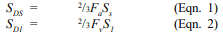
For design purposes, ASCE 7 represents earthquake intensity by means of acceleration response spectra, as shown in Figure 1. Modeling of the ground motion in this manner provides structure-dependent information on the ground motion because buildings respond differently depending on their dynamic characteristics. ASCE 7 contains maps that provide spectral response acceleration values for the maximum considered earthquake ground motion for short period (0.2- second), Ss, and long period (1-second), S1, responses for the entire United States. The design earthquake, in turn, corresponds to two-thirds of the maximum considered earthquake. The spectral response values used for design are then given by:
The site class coefficients, Fa and Fv, depend on the soil properties at the site. ASCE 7 identifies six site classes (A through F) based on soil properties. The mapped spectral are given for Site Class B and modifications must be made to obtain the values for other site classes. Site classification is typically determined by a professional geotechnical engineer at the beginning of a project. However, if the soil properties are not known in sufficient detail to determine the site class, Class D may be used if approved by the building official. Figure 1 shows how the design response spectrum is obtained from the spectral response parameters.
Figure 1—Design Response Spectrum (ref. 2)
Seismic Base Shear
The seismic base shear is the total design lateral force at the base of a building. The base shear is calculated using the design ground motion described in the previous section and modified to account for the structural characteristics and importance placed on a building.
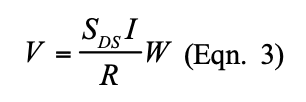
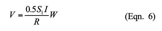
ASCE 7 provides several structural analysis methods for calculating the seismic base shear. This TEK discusses the equivalent lateral force procedure, which is the most commonly used technique for seismic analyses. The equivalent lateral force procedure is a linear static analysis technique that approximates nonlinear building response by use of the response modification factor R, which accounts for a building’s inherent ductility and overstrength. ASCE 7 permits the use of the equivalent lateral force procedure for the design of most buildings, except for those with certain irregularities and buildings with periods greater than 3.5 seconds, such as high-rise buildings. ASCE 7 Table 9.5.2.2 provides values of R for various masonry structural systems. The seismic base shear is given by the following equation:
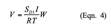
but need not be greater than
The occupancy importance factor, I, is used to ensure that larger forces are used to design buildings for which the consequences of failure may be more severe.
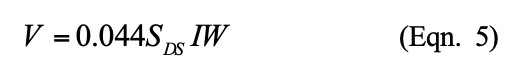
Equations 3 and 4 represent the base shear obtained from the design response spectrum shown in Figure 1, divided by the response modification factor. In addition to these equations, ASCE 7 also stipulates that the design base shear should not be less than:
or, for buildings and structures in Seismic Design Categories E and F, less than:
Vertical Distribution of Seismic Base Shear
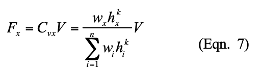
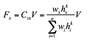
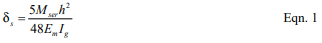
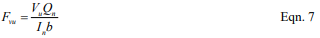
When performing equivalent lateral force analysis, the earthquake load is distributed vertically over the height of the building by applying a portion of the seismic base shear to each level of the building, consistent with the assumption of concentrated floor masses. The force at each level, Fx is given by:
where: k = 1 for T ≤ 0.5 seconds; k = 2 for T ≥ 2.5 seconds. Linear interpolation is used for determining k between 1 and 2 for 0.5 < T < 2.5.
Horizontal Distribution of Seismic Base Shear
Once the seismic force at each floor has been determined from Equation 7, the story shear must be distributed to the lateral load resisting elements at each story. This varies depending on whether the diaphragm is rigid or flexible when compared to the stiffness of the lateral load resisting element. Masonry elements are typically quite stiff and conventional practice is to assume that wood floors and roofs or steel decks without concrete topping are flexible diaphragms. Conversely, concrete and hollow core slabs or steel decks with concrete topping are considered rigid diaphragms.
Figure 2 shows the difference in response of buildings with flexible diaphragms and buildings with rigid diaphragms. With flexible diaphragms, the force is distributed in proportion to the tributary area supported by each wall, whereas the rigid diaphragms distribute the force in proportion to wall stiffness.
Figure 2—Behavior of Rigid and Flexible Diaphragms
Earthquake Loads on Components and Connections
When masonry walls are loaded out-of-plane they act as elements of the structure, or components, that resist the earthquake loads generated by their self-weight. For satisfactory structural response, the wall must span between supports and transfer lateral loads to the floor or roof diaphragm, which in turn transfers the loads to the lateral load resisting system.
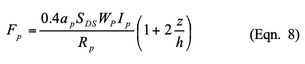
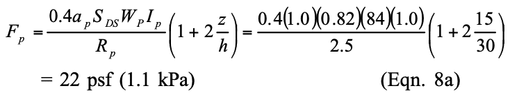
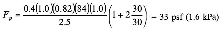
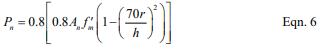
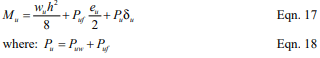
Out-of-plane earthquake loads on masonry walls and their connections are calculated using the requirements of ASCE 7 for components. The following equation is used to determine the seismic design force Fp on the wall, which is distributed relative to the wall mass distribution:
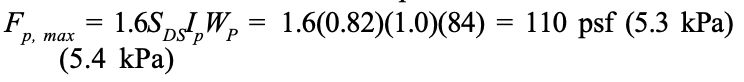
The seismic force need not exceed
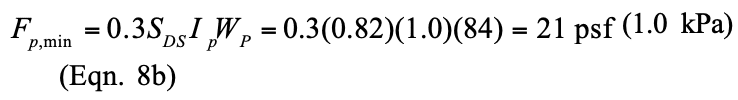
and should not be less than
Figure 3 shows the distribution of earthquake forces over the height of a building when calculated using Equation 8. Since the wall is supported at the bottom and top of each story, the average of the forces calculated for the floor above and the floor below is used to design walls in each story. This ensures that the earthquake forces are applied in proportion to the mass distribution of the wall.
Since earthquake ground motion is cyclic, walls should be evaluated for the out-of-plane demands in both directions to determine the most critical condition. The most severe condition usually occurs when the earthquake loads are applied outward since the eccentricity of the gravity loads from a roof or floor adds to the earthquake induced-moment. In addition, walls should be evaluated for all applicable load combinations in ASCE 7, including load combinations in which the vertical component of the ground motion is negative. This combination usually results in the smallest axial load on a wall and is important to consider since wall capacity and response can be dependent on axial load.
Figure 3—Distribution of Out-of-Plane Earthquake Force over the Height of a Building with Reinforced Masonry Walls
EXAMPLE
Calculate the following earthquake loads on the two-story building constructed with special reinforced masonry shear walls shown in Figure 4:
earthquake load on the seismic force resisting system, and
out-of-plane earthquake load on a typical second story wall.
The building is located at a site with Ss = 1.2g and S1 = 0.4g (SDC D). The building’s occupancy importance factor and component importance factor are equal to 1.0. The site classification for the project is D.
Solution a) earthquake load on the seismic force resisting system
Seismic Weight The portion of the total gravity load of the structure located at the roof and second story is: wroof = 356 kip (1,584 kN) w2 = 571 kip (2,540 kN) The effective seismic weight of the building includes the total dead load plus any other code-prescribed loads. The total effective seismic weight, W, is: W = 356 + 571 = 927 kip (4,124 kN)
Fundamental Period of Vibration In lieu of calculating the building period using a computer analysis, ASCE 7 permits the use of an approximate fundamental period using the following equation: Ta = Cthny The parameters Ct and y are equal to 0.02 and 0.75, respectively, for masonry buildings. Thus,
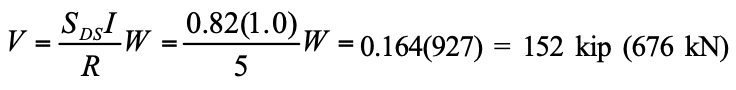
Seismic Base Shear From ASCE 7 Tables 9.4.1.2.4a and Table 9.4.1.2.4b, Fa =1.02, Fv =1.6. Therefore, SDS = ⅔Fa</sub> Ss = 2/3(1.02)(1.2) = 0.82g SD1 = ⅔FvS1 = 2/3(1.6)(0.4) = 0.43gThe seismic base shear is equal to
but need not be greater than
The design base shear should not be less than: V = 0.044SDSIW = 0.044(0.82)(1.0)(927) = 33 kip (147 kN)
Vertical Distribution of Seismic Base Shear The force at each level, Fx is given by:
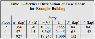
Where k = 1.0 since T = 0.26 seconds, which is less than 0.5 seconds. Table 1 provides the vertical distribution of base shear to the floors of the building. Figure 5 shows the story shear and overturning moment at each floor of the building. At the second story, the steel deck is assumed to act as a flexible diaphragm and the story shear will be distributed to each wall based on the tributary area it supports. The second floor diaphragm with concrete topping is assumed to act as a rigid diaphragm and distributes the earthquake load to the walls in proportion to their stiffness. The engineer should confirm these assumptions by comparing the in-plane deflection of the diaphragms to the lateral displacement of the walls.
Solution b) out-of-plane earthquake load on a typical second story wall
From Equation 8, the out-of-plane seismic pressure attachment at the wall attachment point at the second floor is equal to:
which is less than the maximum pressure of:
and greater than the minimum pressure which is given by:
The pressure at the roof is equal to:
Since the earthquake pressure should be distributed uniformly over the height of the wall in proportion to the wall distribution of mass, the uniformly distributed earthquake pressure in the wall for the second story is equal to:
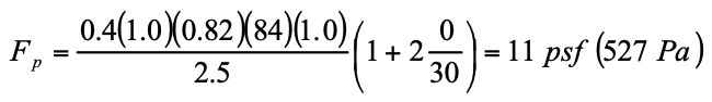
For the first story, the pressure at the wall attachment point at the ground level is:
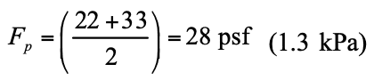
Because this is less than the minimum pressure of 21 psf (1,005 Pa) from Equation 8b, use an average of 21 psf (1,005 Pa) at the ground level and 22 psf (1,053 Pa) previously calculated for the attachment point at the second level:
Fp = (21 + 22)/2 = 22 psf (1,053 Pa)
Figure 6 shows the out-of-plane earthquake forces on the masonry walls. Note that the load on the unbraced parapet is calculated using an amplification factor, ap of 2.5.
Figure 4—Example Masonry Building
Figure 5—Earthquake Loads on Lateral Load Resisting System
Table 1—Vertical Distribution of Base Shear for Example Building
Figure 6—Out-of-Plane Earthquake Loads on Masonry Walls
NOTATIONS
ap amplification factor that represents the dynamic p amplification of the wall relative to the fundamental period of the structure. For most masonry walls, ap = 1.0, except for parapets and unbraced walls for which ap = 2.5. Ct building period coefficient Cvx vertical distribution factor Fa acceleration-based site class modification factor at short periods (0.2 second) Fv velocity-based site class modification factor at long periods (1-second) Fp seismic design force on the wall, psf (kPa) Fx force at each level, kip (kN) h average roof height of structure with respect to the base, ft (m) hi height from the base to level i, ft (m) hn height from the base to the highest level of the structure, ft (m) hx height from the base to level x , ft (m) I occupancy importance factor Ip component importance factor that varies from 1.0 to 1.5 k an exponent related to the structure period: k = 1 for T ≤ 0.5 sec; k = 2 for T ≥ 2.5 sec; use linear interpolation to determine k for 0.5 < T < 2.5 N number of stories in a structure R response modification factor per ASCE 7 Table 9.5.2.2 Rp response modification factor that represents the wall overstrength and ductility or energy absorbing capability. For reinforced masonry walls, Rp = 2.5 while for unreinforced masonry walls, Rp = 1.5. Sa spectral response acceleration Ss 5 percent damped, maximum considered earthquake spectral response acceleration at short periods (0.2- second) S1 5 percent damped, maximum considered earthquake spectral response acceleration at long periods (1-second) SDS 5 percent damped, design spectral response acceleration at short periods (0.2-second) SD1 5 percent damped, design spectral response acceleration at long periods (1-second) T fundamental period of the structure, sec Ta approximate fundamental period of the structure, sec V seismic base shear, kip (kN) W effective seismic weight, kip (kN) Wp wall weight, psf (kPa) wi portion of building effective seismic weight W located at or assigned to level i wx portion of building effective seismic weight W located at or assigned to level x y building period exponent z height of point of wall attachment with respect to the base, ft (m)
REFERENCES
International Code Council (ICC), 2003 International Building Code, International Code Council, Inc., 2002.
Minimum Design Loads for Buildings and Other Structures, ASCE-7-02. American Society of Civil Engineers, 2002.
Prescriptive Seismic Reinforcement Requirements for Masonry Structures, TEK 14-18B. Concrete Masonry & Hardscapes Association, 2003.
Building structural design requires a variety of structural loads to be accounted for: dead and live loads, those from wind, earthquake, lateral soil pressure, lateral fluid pressure as well as forces induced by temperature changes, creep, shrinkage and differential movements. Because any load can act simultaneously with another, the designer must consider how these various loads interact on the wall. For example, an axial load can offset tension due to lateral load, thereby increasing flexural capacity, and, if acting eccentrically, can also increase the moment on the wall. Building codes dictate which load combinations must be considered, and require that the structure be designed to resist the most severe load combination.
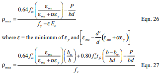
The design aids in this TEK cover combined axial compression or axial tension and flexure, as determined using the strength design provisions of Building Code Requirements for Masonry Structures (ref. 3). For concrete masonry walls, these design provisions are outlined in Strength Design of Concrete Masonry (ref. 1). Axial load-bending moment interaction diagrams account for the interaction between moment and axial load on the design capacity of a wall. This TEK shows the portion of the interaction diagram that applies to the majority of wall designs. Although negative moments are not shown, the figures may be used for these conditions, since with reinforcement in the center of the wall wall strength will be the same under either a positive or negative moment of the same magnitude. Conditions outside of this area may be determined using Concrete Masonry Wall Design Software or Concrete Masonry Design Tables (refs. 4, 5). The reader is referred to Loadbearing Concrete Masonry Wall Design (ref. 2) for a full discussion of interaction diagrams.
Figures 1 through 8 apply to fully or partially grouted reinforced concrete masonry walls with a specified compressive strength f’m of 1,500 psi (10.34 MPa), and a maximum wall height of 20 ft (6.10 m), Grade 60 (414 MPa) vertical reinforcement, with reinforcing bars positioned in the center of the wall and reinforcing bar spacing s from 8 in. to 120 in. ( 203 to 3,048 mm). Figures 1 through 8 apply to fully or partially grouted reinforced concrete masonry walls with a specified compressive strength, f’m, of 1500 psi (10.34 MPa), and a maximum wall height of 20 ft (6.09 m), Grade 60 vertical reinforcement, with reinforcing bars positioned in the center of the wall and reinforcing bar spacing, s, from 8 in. to 120 in. ( 203 to 3,048 mm). Each figure applies to one specific wall thickness and one reinforcing bar size. For walls less than 20 ft (6.1 m) high, figures 1 through 8 will be slightly conservative due to PΔ effects.
Figure 1, Figure 2
Figure 3& Figure 4
Figure 5, Figure 6
Figure 7, Figure 8
DESIGN EXAMPLE
An 8-in. (203-mm) thick, 20 ft (6.10 m) high reinforced simply supported concrete masonry wall (115 pcf (1,842 kg/m³)) is to be designed to resist wind load as well as eccentrically applied axial live and dead loads as depicted in Figure 9. The designer must determine the reinforcement size spaced at 24 in. (610 mm) required to resist the applied loads, listed below.
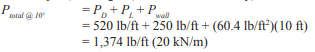
D = 520 lb/ft (7.6 kN/m), at e = 0.75 in. (19 mm) L = 250 lb/ft (3.6 kN/m), at e = 0.75 in. (19 mm) W = 20 psf (1.0 kPa)
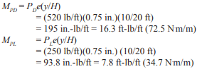
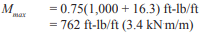
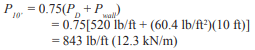
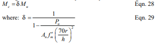
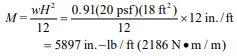
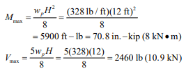
The maximum moment due to the wind load is determined as follows.
The axial load used for design is the axial load at the location of maximum moment. This combination may not necessarily be the most critical section for combined axial load and flexure, but should be close to the critical location. The wall weight is estimated to be halfway between fully grouted and hollow (82 and 38.7 psf (400 and 189 kg/m2), respectively, for 115 pcf (1842 kg/m3) unit concrete density).
The eccentricity of the axial loads also induces bending in the wall and should be included in the applied moment. The magnitude of the moment due to the eccentric axial load must be found at the same location as the maximum moment.
During design, all load combinations should be checked, with the controlling load case used for design. For brevity, only the two combinations above will be evaluated here, since the axial load actually increases the flexural capacity for the first combination by offsetting tension in the wall due to the lateral load.
Figure 2 shows that No. 4 bars at 24 in. (M #13 at 610 mm) on center are adequate. If a larger bar spacing is desired, No. 5 at 32 in. (M #16 at 813 mm) or No. 6 at 48 in. (M #19 at 1219 mm) will also meet the design requirements. Although wall design is seldom governed by out-of-plane shear, the shear capacity should be checked. In addition, the axial load should be recalculated based on the actual wall weight (based on grout spacing chosen), then the resulting required capacity should be recalculated and plotted on the interaction diagram to check adequacy.
Figure 9 -Wall Section for Loadbearing Wall Design Example
NOMENCLATURE
D dead load, lb/ft (kN/m) e eccentricity of axial load – measured from centroid of wall, in. (mm) f’m specified masonry compressive strength, psi (MPa) h height of wall, in. (mm)
L live load, lb/ft (kN/m) Lr roof live load, lb/ft (kN/m)
Mu factored moment, in.-lb/ft or ft-lb/ft (kN⋅m/m) Pu factored axial load, lb/ft (kN/m)
s spacing of vertical reinforcement, in. (mm) W wind load, psf (kN/m²) y distance measured from top of wall, ft (m)
REFERENCES
Strength Design of Concrete Masonry, TEK 14-04B. Concrete Masonry & Hardscapes Association, 2002.
Communities across the nation rely on concrete masonry for their prisons and detention centers. In addition to its strength and durability, the layout of concrete masonry walls and cells can be cost-effectively tailored to meet the facility’s needs. Concrete masonry is a proven product for correctional facilities, providing secure construction with a minimum of long-term maintenance.
Concrete masonry walls designed as security barriers are most often fully grouted and reinforced. Typically, vertical grouted cells with steel reinforcing in every cell are provided, although reinforced horizontal bond beams may also be specified. This type of construction is found in prisons, secure facilities or other areas where the integrity of the building envelope or wall partition is vital to secure an area.
Recent testing (refs. 1, 2) confirms the impact resistance of concrete masonry construction, and quantifies the performance of various concrete masonry wall systems.
IMPACT TESTING
Standard Test Methods for Physical Assault on Fixed Barriers for Detention and Correctional Facilities (ref. 3) is being developed to help quantify levels of security for walls designed to incarcerate inmates in detention and correctional institutions. The standard is intended to help ensure that detention security walls perform at or above minimum acceptable levels to: control passage of unauthorized or secure areas, to confine inmates, to delay and frustrate escape attempts and to resist vandalism.
The test method is intended to closely simulate a sustained battering ram style attack, using devices such as benches, bunks or tables. It addresses only those threats which would be anticipated based on the limited weapons, tools and resources available to inmates within detention and correctional facilities.
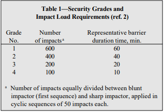
The draft security wall standard includes provisions to test monolithic wall panels as well as wall panels with simulated window openings. The standard assigns various security grades for fixed barriers based on the wall’s ability to withstand the simulated attack (see Table 1). Attack is simulated via a series of impacts from a pendulum testing ram apparatus. The testing ram is fitted with two heads: a blunt impactor to simulate a sledge hammer, and a sharp impactor simulating a fireman’s axe. The testing protocol calls for blows from both the blunt and sharp impactors, applied in sequences of 50 blows each.
Failure of a wall assembly is defined as an opening through the wall which allows a 5 in. x 8 in. x 8 in. (127 x 203 x 203 mm) rigid rectangular box to be passed through the wall with no more than 10 lb (44.5 N) of force.
The draft standard also assigns a representative barrier duration time, based on an historical testing observation that sustained manpower can deliver 400 blows of 200 ft-lb (271.2 J) each in 45 minutes. The element of time assigned to the various security grades is adjusted to achieve more manageable time periods than actual calculations provide. The amount of time is estimated and is offered solely as supplementary design information to assist the user in matching security grades with the attack resistance times and staff response times required for each barrier in the facility.
Table 1—Security Grades and Impact Load Requirements (ref. 2)
CONCRETE MASONRY SECURITY GRADES
Using the test method described above, 8-in. (203- mm) concrete masonry walls, with and without window openings, have been shown to meet the highest security rating, Grade 1, with a representative barrier duration time of at least 60 minutes.
Typical Federal Bureau of Prisons masonry wall systems include: Type A, 8-in. (203-mm) normal weight concrete masonry with No. 4 (M #13) reinforcement at 8 in. (203 mm) on center both vertically and horizontally; and Type B, 8-in. (203-mm) normal weight concrete masonry with No. 4 (M #13) reinforcement at 8 in. (203 mm) on center vertically. Note that although both of these wall designs call for normal weight concrete masonry units, test results on a wall constructed using lightweight units (ref. 1) exceed the minimum requirements for a Grade 1 barrier, as do those for normal weight units.
Test Results
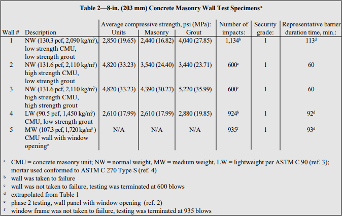
Five concrete masonry wall assemblies were tested (refs. 1, 2), and are described in Table 2. All five concrete masonry walls were able to withstand 600 blows and therefore achieve the Grade 1 rating in accordance with the draft ASTM standard for security walls. Additionally, the back side of each wall assembly was monitored after each sequence of 50 blows and no penetration or damage, including minor cracks, was observed during the 600 blows.
Subsequent to this testing, two of the wall assemblies were taken to failure. That is, walls #1 and #4 were subject to the blunt and sharp impactors in cycles of 50 blows apiece until the forcible breach defined in the draft security wall standard was observed. Wall #1 failed at 1,134 blows. Extrapolating the criteria in the draft ASTM standard, this corresponds to a rating of 1.8 hours. Wall #4 failed at 924 blows, which corresponds to a security rating of approximately 1.5 hours.
Table 2—8-in. (203 mm) Concrete Masonry Wall Test Specimens
Test Specimens
All walls were constructed using 8 in. (203 mm) thick concrete masonry units with grout and one No. 4 (M #13) vertical reinforcing bar in each cell. Typical security wall construction provides stiffness at both the top and bottom of the wall through interconnection with the foundations below and the floor slab above. Rather than constructing individual flat wall panels with both a foundation below and a slab above as well as end returns (simulating stiffness provided by wall intersections), two four-sided closed cells were constructed: one for the wall panels without openings and one for the wall panels with simulated window openings. The walls were grouted into a reinforced concrete foundation and a reinforced concrete cap was used to fix the tops of the concrete masonry walls. Figure 1 shows the test panel configuration for the walls without window openings.
The four wall assemblies without openings differed in the types of concrete masonry units used and/or the grout strength used. These differences are fully described in Table 2. Three of the walls used normal weight concrete masonry units (with a concrete density of approximately 130 pcf (2,082 kg/m³)), and the fourth used lightweight units (with a concrete density of 90.5 pcf (1,450 kg/m³)).
For testing the walls without openings, the impacts were applied to the intersection of a bed and head joint at the midpoint of the wall. This location was chosen to be the predicted weak point of the wall assembly. Therefore, using the testing ram, a series of strikes were set against the target area and each strike was within ± 2 in. (51 mm) horizontally and vertically from the designated target area.
For the panel with the typical prison window frame (ref. 2), the window frame was manufactured to meet Guide Specifications for Detention Security Hollow Metal Doors and Frames, ANSI/HMMA– 863 (ref. 6) as required by the draft ASTM security wall standard. The nominal dimensions of the frame were 14 in. wide, 38 in. high, with a jamb width of 8 ¾ in (356 x 965 x 222 mm). The window frame was constructed of ¼ in. (6.4 mm) thick steel. The frame came equipped with masonry anchors that accommodated the vertical reinforcing bars in the masonry and then attached to the window frame. Once installed, the hollow area at the jamb was grouted solid. The intent of this impact testing is to check the integrity of the frame-to-masonry connection by striking at a corner of the window frame.
Figure 1—Prison Impact Test Wall Configuration
SPECIALIZED CONCRETE MASONRY UNITS FOR PRISON WALL CONSTRUCTION
Concrete masonry units are manufactured in many different shapes and sizes. Although conventional concrete masonry units are often used for prison construction, some specialized units may also be available which are particularly well-suited for prison construction, such as those shown in Figure 2. Shapes intended to easily accommodate vertical and/or horizontal reinforcement include open-ended units and bond beam units. Open-ended units, such as the A- and H- shaped units shown in Figure 2a, allow the units to be threaded around vertical reinforcing bars. This eliminates the need to lift units over the top of the reinforcing bar, or to thread the reinforcement through the masonry cores after the wall is constructed. Horizontal reinforcement and bond beams in concrete masonry walls can be accommodated either by sawcutting out of a standard unit or by using bond beam units (Figure 2b). Bond beam units are either manufactured with reduced webs or with “knock-out” webs, which are removed prior to placement in the wall. Horizontal bond beam reinforcement is easily accommodated in these units.
Figures 2c and 2d show special Y-shaped and corner units developed specifically for prison construction. The Y-shaped units (with one 90° angle and two 135° angles) were developed to allow one corner of a rectangular prison cell to be used as a triangular chase for plumbing, electrical and HVAC service. By truncating the cell corner in this way, all repairs and maintenance can be accomplished without tradesmen ever having to enter the cell, thus reducing additional security risks. The Y-shaped and corner units allow this construction, as well as construction of nonrectangular cells, without creating continuous vertical joints in the wall.
Figure 2—Concrete Masonry Units for Prison Construction
REFERENCES
Prison Wall Impact Investigation. National Concrete Masonry Association, May 2001.
Prison Wall Impact Investigation, Phase 2 . National Concrete Masonry Association, December 2002.
Revision No. 12 Standard Test Methods for Physical Assault on Fixed Barriers for Detention and Correctional Facilities. ASTM International, 2001.
Standard Specification for Loadbearing Concrete Masonry Units, C 90-02. ASTM International, 2002.
Standard Specification for Mortar for Unit Masonry, C 270-02. ASTM International, 2002.
Guide Specifications for Detention Security Hollow Metal Doors and Frames, ANSI/HMMA– 863-98. Hollow Metal Manufacturers Association, 1998.
Hybrid masonry is a structural system that utilizes reinforced masonry infill walls with a framed structure. While the frame can be constructed of reinforced concrete or structural steel, the discussion here will include steel frames in combination with reinforced concrete masonry walls. The masonry walls are used as part of the lateral load resisting system.
Following the development of the wrought iron framed Glass Palace in France in 1851, framed technology evolved and spread to the United States. Since then, combining masonry walls with frames has been used as a common feature of many early building types.
Caged construction was introduced in 1882 by architect George Post. The first caged framed building used a structural steel framework mixed with exterior walls of unreinforced masonry. The term caged walls resulted from the exterior walls being built around a structural cage. The frame supported the floor and roof gravity loads; the masonry was independent of the frame and self-supporting and provided the lateral stiffness. As a result, the wall thicknesses were only slightly less than those in bearing wall buildings.
Another type of structure used exterior unreinforced bearing walls and interior structural frames. The famous Monadnock Building in Chicago, constructed in 1892 is an example of this type with exterior masonry bearing walls up to 6 ft (1.83 m) thick. The 15-story building was the largest office building in the world when completed. Ironically, it was the last high-rise built with exterior masonry bearing walls for the full height of the building and an interior frame.
Transitional buildings were perhaps the most used type of combination frame/masonry structures used through the 1940s. An example is the 13-story Tower Building in New York built in 1888, which used transitional and load bearing construction. Transitional buildings took traditional masonry walls and constructed them integrally with the exterior structural frame. Brick or hollow clay tile was used as an inner wythe, usually 8 in. (203 mm) thick. An exterior wythe of brick, cast stone, terra-cotta or stone was anchored or headered to the backup to function as a composite wall system, but there was no accommodation for the masonry walls to take differential movement. It was common to design these buildings for gravity loads only. While the wall system was not intended to be structural, it provided lateral stiffness. The masonry also provided exterior finish, fire protection for the frame, and backup for the interior finish.
Confined masonry within concrete frames is yet another form of combination structure. This system originated in the 1800s. It has developed globally but apparently has no specific origin. Confined masonry is used primarily for residential construction. The type of masonry infill varies by region or country and includes clay brick, clay tile, stone or concrete masonry.
As framed structures grew taller, architects tried to reduce the thickness of the exterior walls. The structural steel and reinforced concrete structures were used to support building loads and exterior wall loads. Curtain walls and cavity walls developed during this time and masonry was no longer the only wall material used as a backup system for exterior walls.
The concept of using masonry infill to resist lateral forces is not new; having been used successfully throughout the world in different forms. While common worldwide, U.S. based codes and standards have lagged behind in the establishment of standardized means of designing masonry infill.
The hybrid masonry system outlined in this TEK is a unique method of utilizing masonry infill to resist lateral forces. The novelty of the hybrid masonry design approach relative to other more established infill design procedures is in the connection detailing between the masonry and the steel frame, which offers multiple alternative means of transferring loads into the masonry—or isolating the masonry infill from the frame.
Prior to implementing the design procedures outlined in this TEK, users are strongly urged to become familiar with the hybrid masonry concept, its modeling assumptions, and its limitations particularly in the way in which inelastic loads are distributed during earthquakes throughout the masonry and frame system. This system, or design methods, should not be used in Seismic Design Category D and above until further studies and tests have been performed; and additional design guidance is outlined in adopted codes and standards.
HYBRID MASONRY CONCEPT
Since the 1950s, architects and engineers have primarily used cavity walls with framed structures. The backup masonry walls are generally termed infill walls. They support out-of-plane loads on the wall and are isolated from the frame so as not to participate in the lateral load resistance (see Figure 1). Codes usually require that these walls be isolated from the lateral movement of the frame to ensure that lateral loads are not imparted to the masonry.
The hybrid system is a variation of the confined masonry system. It incorporates the beneficial qualities of transitional buildings and the characteristics of cavity wall construction. It differs from cavity wall construction in that the infill masonry walls participate with the frame and provide strength and stiffness to the system. The masonry can be used as single wythe or as cavity wall construction. Hybrid masonry structures are constructed of reinforced masonry, not unreinforced masonry, as was common in transitional buildings.
Hybrid masonry/framed structures were first proposed in print in 2006 (ref. 1). There are several primary reasons for its development. One reason is to simplify the construction of framed buildings with masonry infill. While many designers prefer masonry infill walls as the backup for veneers in framed buildings, there is often a conflict created when steel bracing is required and positioned such that conflicts arise with the masonry infill. This leads to detailing difficulties and construction interferences in trying to fit masonry around the braces. One solution is to eliminate the steel bracing and use reinforced masonry infill as shear wall and bracing.
Hybrid masonry/steel structures also provide structural redundancy that can be utilized to limit progressive collapse. The reinforced masonry infill provides an alternative load path for the frame’s gravity loads, hence providing redundancy. The resulting system is more efficient than either a frame or a bearing wall system alone when subjected to progressive collapse design conditions. If a steel column is damaged in a hybrid structure, gravity loads will transfer to the reinforced masonry. If the masonry is damaged, the gravity load transfers to the frame. There are documented examples from the World Trade Center disaster that illustrate redundancy in transitional buildings (ref. 2).
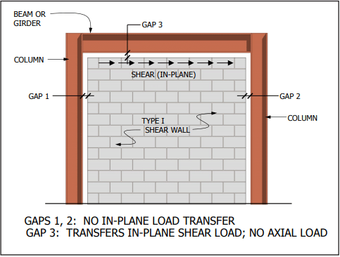
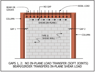
Figure 1—Type I Hybrid Wall
CLASSIFICATION OF WALLS
There are three hybrid wall types. The loadings these walls can support is dependent upon the degree of confinement of the masonry within the frame. These walls can potentially transfer axial loads from the beam/girder of the frame as well as transfer shear from the beam/girder or the columns. The wall systems are defined in Table 1 based on their ability to transfer loads from the frame to the wall. All wall systems listed can address the backup for cavity wall construction. If a veneer is used, it is constructed with relieving angles and is isolated for differential movement as with conventional cavity wall construction. By comparison, an infill wall used in a cavity wall does not transfer axial load or in-plane shear.
The following sections describe each wall type. The key to the performance of the walls is the confinement at the columns and the top of the wall along with the anchorage.
Table 1—Hybrid Masonry Wall Systems
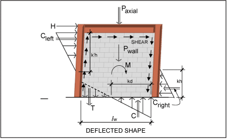
Type I Hybrid Walls
This wall type transmits out-of-plane loads and in-plane shear loads (Figure 1). The gap at the top and the top anchors should not transmit axial loads. If column anchors are used, they should not transmit shear loads. The gaps at the columns must be adequate so the columns do not bear against the masonry when the frame undergoes drift.
All wall types must transfer shear at the base of the wall. This is commonly done using dowels into the foundation or on the framing at the bottom of the wall.
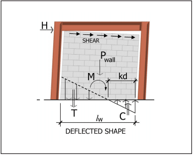
The tie-down forces are a key component to the support of the wall against preventing overturning.
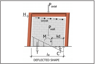
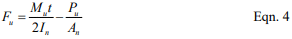
Effectively, the masonry wall is a nonloadbearing shear wall that also supports out-of-plane loads. The in-plane forces are shown in Figure 2. These forces must be applied to the frame design. The tension load T can be accommodated by the distributed reinforcement or the designated tie-down reinforcement. This same reinforcement can be used to distribute shear forces as well. Type I walls can be ideal for buildings up to four stories.
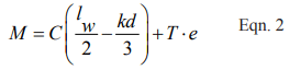
The forces are resolved into:
where e is the eccentricity of the tie-down force, which is defined as the distance between the tie-down reinforcement and the center of the wall.
Figure 2— Type I Force Distribution
Type II Hybrid Walls
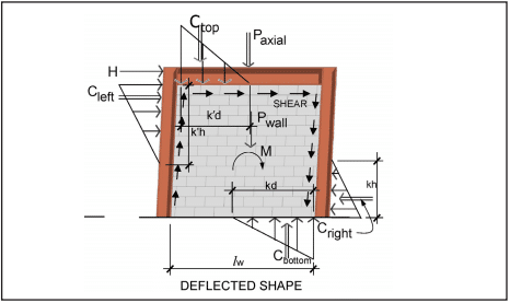
The Type II hybrid wall is a modification of Type I. It is constructed tight to the beam framing above such that axial loads are transmitted to the masonry wall (Figure 3). The top anchors transmit out-of-plane loads and shear loads. If column anchors are used, they do not transmit shear loads.
Effectively, the masonry wall is a loadbearing shear wall that also supports out-of-plane loads.
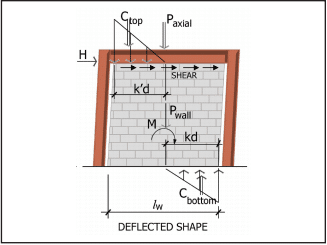
There are two options for distributing the in-plane forces resulting from overturning of the shear wall, designated Type IIa and Type IIb. For Type IIa (Figure 4), the tension load T can be accommodated by the distributed reinforcement or the designated tie-down reinforcement. For Type IIb (Figure 5), the tension force that tied down the wall in the Type IIa wall is replaced by compression on the upper framing and is transferred into the steel frame. This is a significant benefit in multi-story buildings because the tie-down to the frame is not required.
As previously noted, shear dowels are needed at the base of the walls. Type IIb walls, unlike Type I and IIa, do not require tension lap splices for the vertical reinforcement at the base of the walls since only shear loads are being developed.
Type II walls are generally limited to buildings 10 to 14 stories high since masonry stresses will usually govern. Generally, this limitation is similar for loadbearing buildings as well.
The designer has the option to load-share the gravity loads with the masonry wall. This can reduce the size of the beam/girder framing member. For example, if the masonry is constructed after the dead loads of the floor/roof framing system are installed, the masonry wall can take the gravity loads that are added to the structure after the walls are built. The framing (columns and beams/girders) sizes can be limited to support only the dead loads and the lateral load effects. The framing should be designed for the full gravity loads if there is a chance that the wall will be modified in the future.
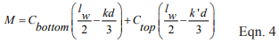
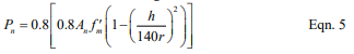
For the Type IIb wall at the base of the wall:
The overturning is resolved by:
The axial load imparted to the wall is a function of the construction sequence. This should be stated in the construction documents. For example, if the steel is designed for only the slab and framing dead load and the lateral load effects, the masonry walls must be constructed tight to the framing above after the slab is in place but before the wall above is started.
The steel framing and the masonry must be designed using similar assumptions.
Figure 3—Type II Hybrid Wall
Figure 4—Type IIa Force Distribution
Figure 5—Type IIb Force Distribution
Type III Hybrid Walls
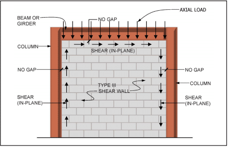
This wall type is fully confined within the framing (Figure 6). It is most similar to the transitional buildings from the early 1900s. However, in this modernized version the masonry is engineered and reinforced to support axial and shear loads in addition to the out-of-plane loads. As with the Type II hybrid wall, the designer has the option to design the columns and beams/girders for the portion of the gravity loads installed before the masonry.
Currently, there are no standards in the United States that govern the design of this type of wall. Research is underway to help define the behavior of these walls, which will lead to code requirements. Designers should only use this system at their own discretion. Statics can be used to generate formulas comparable to Equations 1 through 4 for Type I and II hybrid.
Figures 7 and 8 show the two variations (Type IIIa and Type IIIb) based on how the overturning force is handled.
Figure 6—Type III Hybrid Wall
Figure 7—Type IIIa Force Distribution
Figure 8—Type IIIb Force Distribution
HYBRID DESIGN
As discussed, the masonry in hybrid structures can carry out-of-plane loads in addition to in-plane loads. The masonry design can be performed based on the code for reinforced masonry using allowable stress (based on linear elastic methods). As strength design procedures gain acceptance, load factor design with non-linear elastic evaluation of the masonry will be possible.
While there are three hybrid types that dictate the loadings (Type I, II and III), there are three shear wall types available for the design of the walls themselves. The shear wall type depends on the minimum prescriptive reinforcement and grouting. The Building Code Requirements for Masonry Structures and the International Building Code (IBC) (refs. 3, 4) classify shear walls as ordinary reinforced, intermediate reinforced, or special reinforced. Therefore, there are three combinations of hybrid types to choose from.
The structural steel system design and the in-plane loads to the masonry are based upon the IBC and ASCE 7 (ref. 11) using seismic factors for R (response modification coefficient), Ωo (system over-strength factor), and Cd (deflection amplification factor) applicable to the type of shear walls used with building frames. These factors are given in Table 2. An on-going research project at the University of Illinois is evaluating these factors for their applicability to hybrid walls.
Ordinary reinforced shear walls are permitted in Seismic Design Categories (SDCs) A, B and C. The building height is unlimited for SDCs A and B and limited to 160 ft (48.76 m) for SDC C.
Intermediate reinforced shear walls are permitted in SDCs A, B and C. The building height is unlimited.
Special reinforced shear walls are permitted in all seismic design categories. The building height is unlimited in SDCs A, B and C, limited to 160 ft (48.8 m) in SDCs D and E, and limited to 100 ft (30.5 m) in SDC F.
While these are the permitted types and classes, most projects thus far have been in SDC A, B and C. This has been convenient in that an R = 3 type structural steel design has been used in accordance with AISC. Designs in SDC D and higher would require use of the AISC Seismic Design Manual, AISC 327-05 (ref. 9). In addition, research is on-going for various aspects of the systems in higher seismic classes.
More detailed information on prescriptive seismic detailing for concrete masonry shear walls can be found in TEK 14-18A, Prescriptive Seismic Reinforcement Requirements for Masonry Structures (ref. 10).
Table 2—Factors Based On Shear Wall Type
COMPUTER SOFTWARE
Several commercial software companies have masonry design packages (refs. 5, 6), some of which have included hybrid masonry in their packages. This allows the masonry and steel to be modeled and designed as a system. The software is primarily based on allowable stress design and linear elastic analysis. There are plans to incorporate strength design in the future.
CONCLUSIONS
Hybrid masonry offers many benefits and complements framed construction. By using the masonry as a structural element for in-plane loads, the constructability of the masonry with the frames is improved, the lateral stiffness is increased, the redundancy is improved, and opportunities for reduced construction costs are created.
Designs indicate that greater stiffness can be achieved with hybrid masonry systems in comparison with braced frames or moment frames. The beneficial effect on the framing through the load-sharing abilities of the system is also evident. These qualities, stiffness, and redundancy can be useful in preventing progressive collapse.
For now, Type I and Type II hybrid systems can be designed in the United States using existing codes and standards. Criteria for Type III hybrid systems are under development.
Details for the construction of hybrid walls and design issues related to the top connectors are discussed in TEK 03-03B and IMI Technology Brief 02.13.02 (refs. 7, 8).
NOTATIONS:
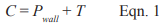
C = resultant compressive force, lb (N) Cbottom = resultant compressive force at bottom of masonry wall, lb (N) Cd = deflection amplification factor Cleft = resultant compressive force on left side of masonry wall, lb (N) Cright = resultant compressive force on right side of masonry wall, lb (N) Ctop = resultant compressive force at top of masonry wall, lb (N) d = distance from extreme compression fiber to centroid of tension reinforcement, in. (mm) e = eccentricity of the tie-down force, equal to the distance of the tie-down reinforcement from the center of the wall, in. (mm) H = shear force, lb (N) h = effective height of masonry element, in. (mm) k, k’ = ratio of distance between compression face of wall and neutral axis to the effective depth, d for the bottom and top of the wall; and to the height of the wall, h, for the sides, respectively. lw = length of entire wall or of segment of wall considered in the direction of shear force, in. (mm) M = maximum moment at the section under consideration, in.-lb (N-mm) Paxial = axial load, lb (N) Pwall = axial load due to wall weight, lb (N) R = seismic response modification factor T = tension in reinforcement, lb (N) Ωo = system over-strength factor
REFERENCES
Biggs, D.T., Hybrid Masonry Structures, Proceedings of the Tenth North American Masonry Conference, The Masonry Society, June 2007.
Biggs, D.T., Masonry Aspects of the World Trade Center Disaster, The Masonry Society, 2004.
Building Code Requirements for Masonry Structures, ACI 530-08/ASCE 5-08/TMS 402-08. The Masonry Society, 2008.
2006 International Building Code. International Code Council, 2006.
RAM Advanse Version 10.0, Masonry Wall, RAM International, 2009.
RISA 3D Version 8.0, RISA Technologies.
Hybrid Masonry Construction With Structural Steel Frames, TEK 03-03B. Concrete Masonry & Hardscapes Association, 2009.
Hybrid Masonry Construction, IMI Technology Brief 02.13.02. International Masonry Institute, 2009.
AISC Seismic Design Manual, AISC 327-05. American Iron and Steel Institute, 2005.
Prescriptive Seismic Reinforcement Requirements for Masonry Structures, TEK 14-18A. Concrete Masonry & Hardscapes Association, 2003.
Minimum Design Loads for Buildings and Other Structures, ASCE 7-05. American Society of Civil Engineers, 2005.
Empirical design is a procedure of proportioning and sizing unreinforced masonry elements based on known historical performance for a given application. Empirical provisions preceded the development of engineered masonry design, and can be traced back several centuries. This approach to design is based on historical experience in lieu of analytical methods. It has proven to be an expedient design method for typical loadbearing structures subjected to relatively small wind loads and located in areas of low seismic risk. Empirical design has also been used extensively for the design of exterior curtain walls and interior partitions.
Using empirical design, vertical and lateral load resistance is governed by prescriptive criteria which include wall height to thickness ratios, shear wall length and spacing, minimum wall thickness, maximum building height, and other criteria, which have proven to be effective through years of experience.
This TEK is based on the provisions of Section 2109 of the International Building Code (IBC) (ref. 1). These empirical design requirements do not apply to other design methods such as allowable stress or limit states design. For empirical design of foundation walls, see TEK 15-01B, Allowable Stress Design of Concrete Masonry Foundation Walls (ref. 2)
APPLICABILITY OF EMPIRICAL DESIGN
The IBC allows elements of masonry structures to be designed by empirical methods when assigned to Seismic Design Category (SDC) A, B or C, subject to additional restrictions described below. When empirically designed elements are part of the seismic lateral force resisting system, however, their use is limited to SDC A.
Empirical design has primarily been used with masonry laid in running bond. When laid in stack bond, the IBC requires a minimum amount of horizontal reinforcement (0.003 times the wall’s vertical cross-sectional area and spaced not more than 48 in. (1,219 mm) apart).
In addition, buildings that rely on empirically designed masonry walls for lateral load resistance are allowed up to 35 ft (10.7 m) in height.
The 2003 IBC restricts empirical design to locations where the basic wind speed (three-second gust, not fastest mile) is less than or equal to 110 mph (79 m/s), as defined in Minimum Design Loads for Buildings and Other Structures, ASCE 7 (ref. 3). A wind speed of this velocity generally applies along the East and Gulf coasts of the United States.
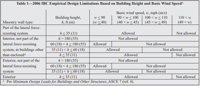
The 2006 IBC further refines the empirical design limitations. Whereas with the 2003 IBC, the designer need only check the SDC and basic wind speed, with the 2006 IBC, to use empirical design the designer must check:
SDC,
basic wind speed,
building height, and
location of gravity loads resultant.
The limitations based on SDC are the same as in the 2003 IBC, described above. Building height and basic wind speed conditions where empirical design is permitted under the 2006 IBC are summarized in Table 1.
The 2006 IBC also requires the resultant of gravity loads to fall within the kern of the masonry element, to avoid imparting tension to the element. This area is defined as: within the center third of the wall thickness, or, for foundation piers, within the central area bounded by lines at one-third of each cross-sectional dimension of the pier.
Table 1—2006 IBC Empirical Design Limitations Based on Building Height and Basic Wind Speed
DESIGN PROVISIONS
Minimum Wall Thickness
Empirically designed (unreinforced) bearing walls of one story buildings must be at least 6 in. (152 mm) thick. For buildings more than one story high, walls must be at least 8 in. (203 mm) thick. The minimum thickness for unreinforced masonry shear walls and for masonry foundation walls is also 8 in. (203 mm). Note that the 2003 IBC allows shear walls of one-story buildings to have a minimum thickness of 6 in. (152 mm).
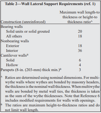
Lateral Support
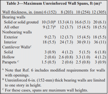
Lateral support for walls can be provided in the horizontal direction by cross walls, pilasters, buttresses and structural frame members, or in the vertical direction by floor diaphragms, roof diaphragms and structural frame members, as illustrated in Figure 1. For empirically designed walls, such support must be provided at the maximum intervals given in Tables 2 and 3. Note that the span limitations apply to only one direction; that is, the span in one direction may be unlimited as long as the span in the other direction meets the requirements of Tables 2 or 3.
Figure 1—Lateral Support of Empirically Designed (Unreinforced) Concrete Masonry Walls
Table 2—Wall Lateral Support Requirements (ref. 1)
Table 3—Maximum Unreinforced Wall Spans, ft (m)
Allowable Stresses
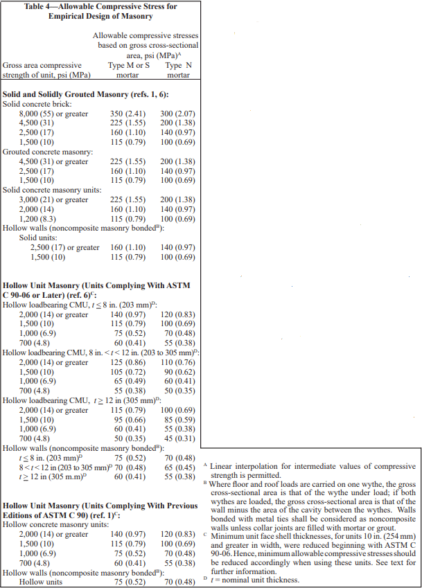
Allowable stresses in empirically designed masonry due to building code prescribed vertical (gravity) dead and live loads (excluding wind or seismic) are given in Table 4.
Table 4 includes two sets of compressive stresses for hollow concrete masonry units (CMU). The first set, titled “Hollow Unit Masonry (Units Complying With ASTM C 90- 06 or Later)” apply to most CMU currently available. The 2006 edition of the CMU specification, Standard Specification for Loadbearing Concrete Masonry Units, ASTM C 90 (ref. 7), included slightly reduced minimum face shell thickness requirements for CMU 10 in. (254 mm) and greater in width. These smaller face shells require a corresponding adjustment to the allowable compressive stresses. The values currently published in the 2006 IBC (“Hollow Unit Masonry (Units Complying With Previous Editions of ASTM C 90)” in Table 4), apply to the previous face shell thicknesses, and should only be used if the CMU to be used have the thicker face shells listed in previous editions of ASTM C 90. This distinction is not applicable to masonry that will be solidly grouted.
Calculated compressive stresses for both single and multiwythe walls are determined by dividing the design load by the gross cross-sectional area of the wall, excluding areas of openings, chases or recesses. The area is based on the specified dimensions of masonry, rather than on nominal dimensions. In multiwythe walls, the allowable stress is determined by the weakest combination of units and mortar shown in Table 4.
In addition, the commentary to Building Code Requirements for Masonry Structures (refs. 6, 8) contains additional guidance for concentrated loads. According to the commentary, when concentrated loads act on empirically designed masonry, the course immediately under the point of bearing should be a solid unit or be filled solid with mortar or grout. Further, when the concentrated load acts on the full wall thickness, the allowable stresses under the load may be increased by 25 percent. The allowable stresses may be increased by 50 percent when concentrated loads act on concentrically placed bearing plates that are greater than one-half but less than the full area.
Table 4—Allowable Compressive Stress for Empirical Design of Masonry
Anchorage for Lateral Support
Where empirically designed masonry walls depend on cross walls, roof diaphragms, floor diaphragms or structural frames for lateral support, it is essential that the walls be properly anchored so that the imposed loads can be transmitted from the wall to the supporting element. Minimum anchorage requirements for intersecting walls and for floor and roof diaphragms are shown in Figures 2 and 3, respectively.
Masonry walls are required to be anchored to structural frames that provide lateral support by ½ in. (13 mm) diameter bolts spaced at a maximum of 4 ft (1.2 m), or with other bolts and spacings that provide equivalent anchorage. The bolts must be embedded a minimum of 4 in. (102 mm) into the masonry.
In addition, the 2006 IBC requires the designer to check the roof loading for net uplift and, where net uplift occurs, to design the anchorage system to entirely resist the uplift.
Figure 2—Empirical Anchorage Requirements for Lateral Support of Intersecting Masonry Walls
Figure 3—Empirical Anchorage Requirements for Floor and Roof Diaphragms
Shear Walls
Where the structure depends on masonry walls for lateral stability against wind or earthquake forces, shear walls must be provided parallel to the direction of the lateral forces as well as in a perpendicular plane, for stability.
Requirements for empirically designed masonry shear walls are shown in Figure 4.
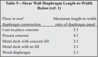
Shear wall spacing is determined empirically by the length-to-width aspect ratio of the diaphragms that transfer lateral forces to the shear walls, as listed in Table 5. In addition, roofs must be designed and constructed in a manner such that they will not impose thrust perpendicular to the shear walls to which they are attached.
The height of empirically designed shear walls is not permitted to exceed 35 ft (10.7 m). The minimum nominal thickness of shear walls is 8 in. (203 mm), except under the 2003 IBC, which allows shear walls of one-story buildings to have a minimum thickness of 6 in. (152 mm).
Figure 4—Empirically Designed Shear Wall Requirements
Wythes of multiwythe masonry walls are required to be bonded together. Bonding can be achieved using masonry headers, metal wall ties, or prefabricated joint reinforcement, as illustrated in Figure 5. Various empirical requirements for each of these bonding methods are given below.
Bonding of solid unit walls with masonry headers. Where masonry headers are used to bond wythes of solid masonry construction, at least 4 percent of the wall surface of each face must be composed of headers, which must extend at least 3 in. (76 mm) into the backing. The distance between adjacent full-length headers may not exceed 24 in. (610 mm) in either the horizontal or vertical direction. In walls where a single header does not extend through the wall, headers from opposite sides must overlap at least 3 in. (76 mm), or headers from opposite sides must be covered with another header course which overlaps the header below by at least 3 in. (76 mm).
Bonding of hollow unit walls with masonry headers. Where two or more hollow units are used to make up the thickness of a wall, the stretcher courses must be bonded at vertical intervals not exceeding 34 in. (864 mm) by lapping at least 3 in. (76 mm) over the unit below, or by lapping at vertical intervals not exceeding 17 in. (432 mm) with units that are at least 50 percent greater in thickness than the units below.
Bonding with metal wall ties (other than adjustable ties). Wire size W2.8 (MW18) wall ties, or metal wire of equivalent stiffness, may be used to bond wythes. Each 4½ ft² (0.42 m²) of wall surface must have at least one tie. Ties must be spaced a maximum of 24 in. (610 mm) vertically and 36 in. (914 mm) horizontally. Hollow masonry walls must use rectangular wall ties for bonding. In other walls, ends of ties must be bent to 90° angles to provide hooks no less than 2 in. (51 mm) long. Additional bonding ties are required at all openings, and must be spaced a maximum of 3 ft (914 mm) apart around the perimeter and located within 12 in. (305 mm) of the opening. Note that wall ties may not include drips, and that corrugated ties may not be used.
Bonding with adjustable ties. Adjustable ties must be spaced such that there is one tie for each 1.77 ft² (0.164 m²) of wall area, with maximum horizontal and vertical spacings of 16 in. (406 mm). The ties must have a maximum clearance between connecting parts of 1/16 in. (1.6 mm), and, when pintle legs are used, at least two legs with a minimum wire size of W2.8 (MW18). The bed joints of the two wythes may have a maximum vertical offset of no more than 1¼ in. (32 mm). (See Reference 9 for an illustration of these requirements.)
Bonding with prefabricated joint reinforcement. Where adjacent wythes of masonry are bonded with prefabricated joint reinforcement, there must be at least one cross wire serving as a tie for each 2⅔ ft² (0.25 m²) of wall area. The joint reinforcement must be spaced 24 in. (610 mm) or closer vertically. Cross wires on prefabricated joint reinforcement must be at least wire size W1.7 (MW11) and shall be without drips. The longitudinal wires must be embedded in the mortar.
Figure 5—Types of Bonding
Change in Wall Thickness
Whenever wall thickness is decreased, at least one course of solid masonry, or special units or other construction, must be placed under the thinner section to ensure load transfer to the thicker section below.
Miscellaneous Empirical Requirements
Following are additional empirical requirements in Building Code Requirements for Masonry Structures. Although not included explicitly in IBC Section 2109, the IBC includes a direct reference to Building Code Requirements for Masonry Structures.
Chases and Recesses Masonry directly above chases or recesses wider than 12 in. (305 mm) must be supported on lintels.
Lintels Lintels are designed as reinforced beams, using either the allowable stress design or the strength design provisions of Building Code Requirements for Masonry Structures. End bearing must be at least 4 in. (102 mm), although 8 in. (203 mm) is typical.
Support on Wood Empirically designed masonry is not permitted to be supported by wood girders or other forms of wood construction, due to expected deformations in wood from deflection and moisture, causing distress in the masonry, and due to potential safety implications in the event of fire.
Corbelling When corbels are not designed using allowable stress design or strength design, they may be detailed using the empirical requirements shown in Figure 6. Only solid or solidly grouted masonry units may be used for corbelling.
Figure 6—Prescriptive Requirements for Corbelling
EMPIRICALLY DESIGNED PARTITION WALLS
In many cases, the building structure is designed using traditional engineered methods, such as strength design or allowable stress design, but the interior nonloadbearing masonry walls are empirically designed. In these cases, the partition walls are supported according to the provisions listed in Tables 2 and 3, but it is important that the support conditions provide isolation between the partition walls and the building’s structural elements to prevent the building loads from being transferred into the partition. The anchor, or other support, must provide the required lateral support for the partition wall while also allowing for differential movement. This is in contrast to the “Anchorage for Lateral Support” section, which details anchorage requirements to help ensure adequate load transfer between the building structure and the loadbearing masonry wall.
Figure 7 shows an example of such a support, using clip angles. C channels or adjustable anchors could be used as well. The gap at the top of the wall should be between ½ and 1 in. (13 and 25 mm), or as required to accommodate the anticipated deflection. The gap is filled with compressible filler, mineral wool or a fire-rated material, if required. Fire walls may also require a sealant to be applied at the bottom of the clip angles. This joint should not be filled with mortar, as it may allow load transfer between the structure and the partition wall.
Figure 7—Example of Support for Empirically Designed Masonry Partition Wall
REFERENCES
International Building Code. International Code Council, 2003 and 2006.
Allowable Stress Design of Concrete Masonry Foundation Walls, TEK 15-01B. Concrete Masonry & Hardscapes Association, 2001.
Minimum Design Loads for Buildings and Other Structures, ASCE 7-02. New York, NY: American Society of Civil Engineers, 2002.
Minimum Design Loads for Buildings and Other Structures, ASCE 7-05. New York, NY: American Society of Civil Engineers, 2005.
Masonry Designer’s Guide, 5th Edition. Council for Masonry Research and The Masonry Society, 2007.
Building Code Requirements for Masonry Structures, ACI 530-08/ASCE 5-08/TMS 402-08. Reported by the Masonry Standards Joint Committee, 2008.
Standard Specification for Loadbearing Concrete Masonry Units, ASTM C 90-06. ASTM International, Inc., 2006.
Building Code Requirements for Masonry Structures, ACI 530/ASCE 5/TMS 402. Reported by the Masonry Standards Joint Committee, 2002 and 2005.
Anchors and Ties for Masonry, TEK 12-01B. Concrete Masonry & Hardscapes Association, 2008.
Floor and Roof Connections to Concrete Masonry Walls, TEK 05-07A. Concrete Masonry & Hardscapes Association, 2001.
Varying the bond or joint pattern of a concrete masonry wall can create a wide variety of interesting and attractive appearances using standard units as well as sculptured-face and other architectural units. Because concrete masonry is often used as the finished wall surface, the use of bond patterns other than the traditional running bond has steadily increased for both loadbearing and nonloadbearing walls.
Building code allowable design stresses, lateral support, and minimum thickness requirements for concrete masonry are based primarily on structural testing and research on wall panels laid in running bond construction. When a different bond pattern is used it is advisable to consider its influence on the compressive and flexural strength of a block wall. Some building codes provide for variations in bond pattern to some extent by requiring the use of horizontal reinforcement, for example, when walls are laid in stack bond.
STACK BOND CONSTRUCTION
Excluding running bond construction, the most popular and widely used bond pattern with concrete masonry units is stack bond. Compressive strength is similar for stack and running bond construction. In stack bond masonry, heavy concentrated loads will be carried down to the support by the particular vertical tier or “column” of masonry under the load, with little distribution to adjacent masonry. Stability will not be jeopardized if allowable stresses are not exceeded, but the use of reinforced bond beams will aid in distributing concentrated loads. The use of pilasters or grouted cells will also be effective in increasing the resistance to concentrated loads.
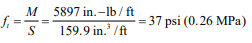
The flexural strength of stack bond walls spanning horizontally can be increased significantly by the use of bond beams or joint reinforcement. The value of joint reinforcement as a means of strengthening concrete masonry in the horizontal span is indicated in Figure 4 which shows the relative flexural strength with and without joint reinforcement. From this it can be seen that properly reinforced stack bond masonry can be designed to be as strong as running bond construction.
CODE REQUIREMENTS
Building Code Requirements for Masonry Structures (ref. 1) includes criteria for walls laid in stack bond. Although stack bond typically refers to masonry constructed such that the head joints are vertically aligned, the Code defines stack bond as masonry laid such that the head joints in successive courses are horizontally offset less than one quarter the unit length, as illustrated in Figure 1.
All stack bond construction is required to have a minimum area of horizontal reinforcement equal to 0.00028 times the gross vertical cross-sectional area of the wall. This requirement can be met using either bond beams spaced not more than 48 in. (1219 mm) on center or using joint reinforcement. Anchored masonry veneer must have horizontal joint reinforcement, of at least one wire size W1.7 (9 gauge) (MW11) or larger, spaced at a maximum of 18 in. (457 mm) on center vertically. This is equivalent to the minimum reinforcement stated above for a nominal 4 in. (102 mm) wythe.
When stack bond construction may be subjected to seismic loads or winds of hurricane velocity, consideration must be given to additional requirements and restrictions as may be consistent with local codes, local experience, and engineering practice. For example, Building Code Requirements for Masonry Structures requires stack bond masonry in Seismic Design Category D and higher to be solidly grouted hollow open-end units, fully grouted hollow units with full head joints, or solid units with a maximum spacing of 24 in. (610 mm) for the reinforcement. Seismic Design Category E & F have an additional requirement that the horizontal reinforcement be at least 0.0015 the gross cross-sectional area of walls that are not part of the lateral-force resisting system. For walls that are part of the lateral force resisting system in SDC E & F, the minimum horizontal reinforcement requirement is increased to 0.0025 times the gross cross-sectional area with a maximum spacing of 16 in. (406 mm). These elements also must be solidly grouted hollow open end units or two wythes of solid units.
Figure 1—Definition of Stack Bond Masonry
TESTING PROGRAM
To assist in evaluating the structural performance of walls laid with various bond patterns, a large number of concrete masonry panels were tested for compressive and flexural strength (ref. 2). The nine bond patterns shown in Figure 2 were employed in constructing the test panels. Panels were composed of 8 in. (203 mm) hollow units laid up with Types M and S mortar with face shell bedding. Panels were 4 ft wide by 8 ft high (1.2 by 2.4 m); those for flexural strength tests with the wall spanning horizontally between supports were 8 ft wide by 4 ft high (2.4 by 1.2 m). For compressive strength tests, loading was applied at an eccentricity of one-sixth of the wall thickness. Lateral tests used uniformly distributed loading from a plastic bag filled with air. Test methods and details followed those specified in Standard Methods of Conducting Strength Tests of Panels for Building Construction, ASTM E 72 (ref. 3)
Relative strengths of the wall panels are compared by bond pattern in Figure 3 using 8 in. (203 mm) high units laid in running bond as the standard.
Figure 2—Concrete Masonry Patterns for Structural Tests
Compressive Strengths
From Figure 3 it is evident that where hollow units are laid in the horizontal position there is no decrease in wall compressive strength for the different bonding patterns. Units laid in the vertical or diagonal position generally produce wall strengths approximately 75% of that obtained from the running bond pattern. The reduction in strength for vertical stack bond is directly related to the decrease in net block area in compression. In the vertical position, the end webs and interior webs are so oriented with respect to the direction of stress that they do not contribute to the strength of the wall except as ties between the face shells. When blocks are laid in the horizontal position, the end and middle webs are parallel to the direction of stress and contribute to the strength of the wall.
Figure 3—Relative Strengths of Walls Laid in Different Bond Patterns
Vertical Span Flexural Strength
Where walls span vertically between lateral supports, failure from transverse loading occurs as a bond failure between block and mortar. Only three of the bond patterns tested showed a decrease in flexural strength when compared to the standard: vertical stack, basket weave “B”, and coursed ashlar. In two of these patterns the continuous horizontal joints are farther apart than the standard running bond pattern. Horizontal stack bond construction was 30% stronger in vertical span flexure, and walls built with units laid in a diagonal position were more than 50% stronger because more mortar bond area is included in the “saw-tooth” line across the wall width.
Horizontal Span Flexural Strength
For unreinforced concrete masonry laid in running bond and spanning horizontally between lateral supports, flexural resistance depends on the strength and design of the block. Under increasing lateral load the units will rupture in tension rather than failing by mortar bond. For this reason, walls are generally at least twice as strong in flexure when spanning horizontally. This does not apply to walls laid in stack bond, which have approximately the same strength in both directions. Test results shown in Figure 4 indicate that the relative strength of stack bond walls in the horizontal span is about 30% of running bond construction.
Figure 4—Relative Flexural Strength in Horizontal Span of Concrete Masonry Walls With and Without Joint Reinforcement
REFERENCES
Building Code Requirements for Masonry Structures, ACI 530-02/ASCE 5-02/TMS 402-02. Reported by the Masonry Standards Joint Committee, 1999.
Structural design of buildings requires a variety of structural loads to be accounted for: dead and live loads, those from wind, earthquake, lateral soil pressure, lateral fluid pressure, as well as forces induced by temperature movements, creep, shrinkage, and differential movements. Because any load can act simultaneously with another, the designer must consider how these various loads interact on the wall. For example, an axial load can offset tension due to lateral load, thereby increasing flexural capacity, and, if acting eccentrically, can also increase the moment on the wall. Building codes dictate which load combinations must be considered, and require that the structure be designed to resist the most severe load combination.
The design aids in this TEK cover combined axial compression or axial tension and flexure, as determined using the allowable stress design provisions of Building Code Requirements for Masonry Structures (ref. 1). The data in this TEK applies to 8 in. (203 mm) thick reinforced concrete masonry walls with a specified compressive strength, f’m, of 1500 psi (10.3 MPa), and a maximum wall height of 20 ft (6.1 m) (taller walls can be evaluated using the NCMA computer software (ref. 3) or other design tools). Reinforcing bars are assumed to be located at the center of the wall, and bar sizes 4, 5, 6, 7, and 8 are included.
AXIAL LOAD-BENDING MOMENT INTERACTION DIAGRAMS
Several design approaches are available for combined axial compression and flexure, most commonly using computer programs to perform the necessary iterative calculations, or using interaction diagrams to graphically determine required reinforcement for the given conditions. Axial load–bending moment interaction diagrams account for the interaction between moment and axial load on the design capacity of a reinforced (or unreinforced) masonry wall.
Figure 1—Full Axial Load-Bending Moment Interaction Diagram (Ref. 2), Dashed Box Indicates Region Displayed In Figures 3 Through 7
Regions of the Interaction Diagram
The various interaction diagram regions are discussed below. Figure 2 shows a typical interaction diagram for a reinforced masonry wall subjected to combined axial load and bending moment. Three distinct regions (I, II and III) can be identified, each with very different characteristics and behavior.
Region I represents the range of conditions corresponding to an uncracked section. That is, there is no tendency for the wall to go into tension, hence the design is governed by masonry compressive strength. Because the Building Code Requirements for Masonry Structures (ref. 1) only permits reinforcing steel to carry an allowable compression stress if it is laterally tied, and since it is generally not practical to do so, the reinforcing steel is simply neglected.
Region II is characterized by cracking in the section, but the reinforcing steel remains subject to compression strain. Hence in Region II, as in Region I, the reinforcing steel is ignored – i.e., the size and location of reinforcing steel are irrelevant. Since the section is cracked, the properties of the cross-section change as the eccentricity changes.
Region III corresponds to values of 0 ≤ k ≤ 1 (tension governs the design). This is the only region where the reinforcing steel affects the capacity of the section.
The load capacity can also be limited by wall slenderness if the eccentricity is sufficiently small and the slenderness sufficiently large. The horizontal line shown in Figure 2 in Region I illustrates the effect of this upper limit on the interaction diagram.
A complete discussion of interaction diagrams, including the governing equations for the various regions, is included in Concrete Masonry Design Tables (ref. 2).
Figure 2—Interaction Diagram of Fully Grouted Reinforced Wall Showing Three Regions
Figures 3 Through 7
Figures 3 through 7 are axial load-bending moment interaction diagrams for reinforcing bar sizes No. 4, 5, 6, 7 and 8, respectively, which can be used to aid in the design of both fully and partially grouted 8 in. (203 mm) single wythe concrete masonry walls. Rather than the full interaction diagram, only the portion outlined by the dashed box in Figure 1 is shown. With reinforcing steel located in the center of the wall, wall strength will be the same under either a positive or negative moment of the same magnitude. Therefore, although negative moments are not shown, the figures may be used for these conditions.
This area of the interaction diagram covers the majority of design applications. Conditions outside of this area may be determined using Concrete Masonry Design Tables (ref. 2). Each line on the diagram represents a different reinforcing bar spacing, included at 8 in. (203 mm) increments.
Building Code Requirements for Masonry Structures (ref. 1) permits a ⅓ increase in allowable stresses when load combinations include wind or seismic loads. Figures 3 through 7 represent load combinations excluding wind or seismic (i.e., no increase in allowable stresses is included). However, these diagrams can be used for load combinations including wind or seismic by multiplying the total applied axial load and moment by 0.75 (see Design Example section).
These interaction diagrams also conform to the International Building Code (ref. 4) basic load combinations for allowable stress design (not including 1/3 stress increase for for wind or seismic). A stress increase is allowed under the IBC alternative basic load combinations but is applied in a different manner than in MSJC. Therefore, the IBC 1/3 stress increase cannot be used in conjunction with these tables.
Figure 3—Interaction Diagram of 8 in. (203 mm) Concrete Masonry Wall With No. 4 Reinforcing Bars
Figure 4—Interaction Diagram of 8 in. (203 mm) Concrete Masonry Wall With No. 5 Reinforcing Bars
Figure 5—Interaction Diagram of 8 in. (203 mm) Concrete Masonry Wall With No. 6 Reinforcing Bars
Figure 6—Interaction Diagram of 8 in. (203 mm) Concrete Masonry Wall With No. 7 Reinforcing Bars
Figure 7—Interaction Diagram of 8 in. (203 mm) Concrete Masonry Wall With No. 8 Reinforcing Bars
DESIGN EXAMPLE – LOADBEARING WALL
A 20 ft (6.1 m) high reinforced concrete masonry wall is to be designed to resist wind load as well as eccentrically applied axial live and dead loads as depicted in Figure 8. The designer must determine the reinforcement size and spacing required to resist the applied loads, listed below.
D = 520 lb/ft (7.6 kN/m), at e = 0.75 in. (19 mm) L = 250 lb/ft (3.6 kN/m), at e = 0.75 in. (19 mm) W = 20 psf (1.0 kPa)
The maximum moment due to the wind load is determined as follows.
The axial load used for design is the axial load at the location of maximum moment. This combination may not necessarily be the most critical section for combined axial load and flexure, but should be close to the critical location. The wall weight is estimated to be halfway between fully grouted and hollow (82 and 38.7 psf (400 and 189 kg/m²), respectively, for 115 pcf (1842 kg/m³) unit concrete density).
The eccentricity of the axial loads also induces bending in the wall and should be included in the applied moment. The magnitude of the moment due to the eccentric axial load must be found at the same location as the maximum moment.
The induced bending moments due to the eccentric axial loads are insignificant compared to that due to wind. However, these will be taken into account where appropriate for specific load combinations.
The applicable load combinations (ref. 1) for this example are:
D + L D + L + W D + W
During design, all three load combinations should be checked, with the controlling load case used for design. For brevity, only the third combination (D + W) will be evaluated here, since the axial load actually increases the flexural capacity for the first two combinations by offsetting tension in the wall due to the lateral load. Because the interaction diagrams in this TEK are for load combinations excluding wind or seismic, the total moment, shear and axial loads the wall must resist (listed below) are multiplied by 0.75 to account for the ⅓ increase in allowable stresses permitted by section 2.1.1.1.3 in Building Code Requirements for Masonry Structures (ref. 1).
To determine the required reinforcement size and spacing to resist these loads, P10’ and Mmax are plotted on the appropriate interaction diagram(s) until a satisfactory design is found.
Figure 3 shows that No. 4 bars at 32 in. (813 mm) on center are adequate. If a larger bar spacing is desired, No. 5 bars at 48 in. (1219 mm) on center will also meet the design requirements (see Figure 4). Although wall design is seldom governed by out-of-plane shear, the shear capacity should be checked. In addition, the axial load should be recalculated based on the actual wall weight (based on grout spacing chosen), then the resulting required capacity should be recalculated and plotted on the interaction diagram to check adequacy.
Figure 8—Wall Section for Loadbearing Wall Design Example
NOMENCLATURE
An net cross sectional area of masonry, in.²/ft (mm²/m) D dead load, lb/ft (kN/m) d distance from extreme compression fiber to centroid of tension reinforcement, in. (mm) e eccentricity of axial load – measured from centroid of masonry unit, in. (mm) Fa allowable compressive stress due to axial load only, psi (MPa) Fb allowable masonry compressive stress due to flexure only, psi (MPa) Fs allowable steel tensile stress, psi (MPa) fy yield stress of steel, psi (MPa) f’m specified masonry compressive strength, psi (MPa) H height of wall, ft (m) k ratio of the distance between compression face of wall and neutral axis to the effective depth, d L live load, lb/ft (kN/m) M moment acting on section, in.-lb/ft or ft-lb/ft (kN m/m) P axial force or concentrated load, lb/ft (kN/m) Pb axial force corresponding to balanced condition, lb (kN) Po maximum axial force ordinate on interaction diagram, lb (kN) s reinforcement spacing, in. (mm) t thickness of masonry, in. (mm) tnom nominal wall thickness, in. (mm) V shear acting at a section, lb/ft (kN/m) W wind load, psf (kN/m²) y distance measured from top of wall, ft (m)
METRIC CONVERSIONS
To convert:
To metric units:
Multiply English units by:
ft
m
0.3048
ft-lb/ft
N m/m
4.44822
in.
mm
25.4
lb/ft
N/m
14.5939
psi
MPa
0.00689476
REFERENCES
Building Code Requirements for Masonry Structures, ACI 530/ASCE 5/TMS 402. Reported by the Masonry Standards Joint Committee, 1999/2002/2005.
International Building Code. International Codes Council, Falls Church, VA, 2000/2003/2006.
Concrete masonry elements can be designed using one of several methods in accordance with Building Code Requirements for Masonry Structures (ref. 1): empirical design, strength design or allowable stress design. This TEK provides a basic overview of design criteria and requirements for concrete masonry structures designed using the strength design provisions contained in Chapter 3 of the 2002 edition of Building Code Requirements for Masonry Structures (also referred to as the MSJC Code) (ref. 1) as referenced and modified in Section 2108 of the 2003 International Building Code (IBC) (ref. 2). In addition, changes to the strength design method incorporated into the 2005 edition of the MSJC Code (ref. 3) through Section 2108 of the 2006 International Building Code (ref. 4) are also reviewed, as are modifications included in the 2008 MSJC Code (ref. 5).
For empirical and allowable stress design requirements, the user is referred to TEK 14-08B, Empirical Design of Concrete Masonry Walls (ref. 6), and TEK 14-07C, ASD of Concrete Masonry (2012 IBC & 2011 MSJC) (ref. 7), respectively. Tables, charts, and additional design aids specific to the design of various concrete masonry elements can be found in other related TEK.
Strength design is based on the following design assumptions in conjunction with basic principles of engineering mechanics (refs. 1, 3, 5), as shown in Figure 1 for a reinforced element:
Plane sections before bending remain plane after bending. Therefore, strain in the masonry and in reinforcement, if present, is directly proportional to the distance from the neutral axis.
For unreinforced masonry, the flexural stresses in the masonry are assumed to be directly proportional to strain. For reinforced masonry, the tensile strength of the masonry is neglected when calculating flexural strength, but considered when calculating deflection.
The units, mortar, grout and reinforcement for reinforced masonry act compositely to resist applied loads.
The nominal strength of masonry cross-sections for combined flexure and axial load is based on applicable conditions of equilibrium.
The maximum masonry compressive stress is 0.80f’m for both reinforced and unreinforced masonry.
The maximum usable strain, εmu, at the extreme compression fiber of concrete masonry is 0.0025.
For reinforced masonry, compression and tension stresses in the reinforcement below the specified yield strength, fy, are taken equal to the modulus of elasticity of the reinforcement, Es, times the steel strain εs. For strains greater than the yield strain corresponding to fy, stress in the reinforcement is taken equal to fy.
For reinforced masonry, the compressive stress is rectangular and uniformly distributed over an equivalent compression zone, bounded by the compression face of the masonry with a depth of a = 0.80c.
Based on the prescribed design model outlined above, the internal distribution of stresses and strains is illustrated in Figure 1 for a reinforced masonry element. A more comprehensive review of the design model is provided in Masonry Structures, Behavior and Design (ref. 8).
Figure 1—Stress and Strain Distribution for Strength Design of Reinforced Masonry
2003 IBC STRENGTH DESIGN MODIFICATIONS
The 2003 IBC adopts the 2002 MSJC Code with two modifications specific to the strength design procedure in IBC Section 2108. The two modifications are as follows.
Section 2108.2 introduces a maximum effective compression width for out-of-plane bending of six times the nominal wall thickness, not to exceed the reinforcement spacing. This is similar to limits historically used by the allowable stress design provisions in the MSJC Code as well as those adopted into the 2005 MSJC Code for strength design, as reviewed below.
Welded and mechanical splices incorporated into masonry elements designed by the strength design method must also comply with Section 2108.3 of the 2003 IBC. For welded splices, the reinforcement to be welded must comply with ASTM A 706 (ref. 9). Splicing by mechanical connectors is classified as either Type 1 or Type 2 mechanical splices in accordance with ACI 318, Building Code Requirements for Structural Concrete (ref. 10). Type 1 mechanical splices are only required to develop 125 percent of the nominal yield strength of the reinforcement being spliced. Type 2 mechanical splices, conversely, must develop the full specified tensile strength of the reinforcement. Welded and Type 1 mechanical splices are not permitted to be used in the plastic hinge region of intermediate or special reinforced masonry shear walls.
2002 MSJC CODE STRENGTH DESIGN CRITERIA
Using strength design, the design strength of a masonry element is compared to the required (or factored) strength (indicated by the subscript u), which includes load factors to account for the uncertainty in predicting design loads and the probability of more than one design load acting simultaneously. The required strength is based on the strength design load combinations as required by Section 1605 of the IBC. At the option of the designer, or when the MSJC Code is used in conjunction with another building code that does not contain load combinations, masonry structures are designed to resist the load combination specified in ASCE 7, Minimum Design Loads for Buildings and Other Structures (ref. 11). For strength design, these load combinations are effectively the same.
The design strength of masonry is the nominal strength (indicated by the subscript n) multiplied by an appropriate strength reduction factor, Φ. The design is acceptable when the design strength equals or exceeds the factored strength (i.e., when ΦMn ≥ Mu) for all prescribed load combinations. The following sections cover the general strength design requirements applicable to both unreinforced and reinforced masonry assemblies, with the exception of design requirements for anchor bolts and lap splices. For these topics, the user is referred to TEK 12-03C, Design of Anchor Bolts Embedded in Concrete Masonry (ref. 12) and TEK 12-06A, Splices, Development and Standard Hooks for CM Based on the 2009 & 2012 IBC (ref. 13), respectively.
Strength Reduction Factors
To account for uncertainties in construction, material properties, calculated versus actual strengths and anticipated failure modes, the nominal strength of a masonry element is multiplied by an appropriate strength reduction factor, Φ. Strength reduction factors are used in conjunction with the load factors applied to the design loads. The values of the strength reduction factors for various types of loading conditions are:
for reinforced masonry elements subjected to flexure or axial loads; Φ = 0.90;
for unreinforced masonry elements subjected to flexure or axial loads; Φ = 0.60;
for masonry elements subjected to shear loads; Φ = 0.80;
for bearing on masonry elements; Φ = 0.60.
Drift and Deflection
When designing for earthquakes, the story drift (the relative displacement of adjacent stories) must be checked against the IBC prescribed allowable story drifts. When the MSJC Code is used in conjunction with a building code that does not contain allowable story drifts, the provisions of ASCE 7 are used. For masonry buildings with cantilevered shear walls, the IBC limits the story drift to 0.01hsx, where hsx is the height of the story below the level for which the drift is being calculated. For other types of masonry shear wall buildings, except masonry frames, the allowable story drift is limited to 0.007hsx. While the IBC includes story drift limits for masonry frame wall buildings, such structural configurations are rarely used. When calculating story drift, the calculated elastic deflection is multiplied by the deflection amplification factor, Cd, as prescribed in the IBC for the type of structural system being designed. The deflection amplification factor approximates the additional deflection due to inelastic response (if applicable) of the system during an earthquake. Due to the inherent in-plane stiffness of masonry assemblies, in-plane deflection and story drift are rarely a controlling limit unless a relatively large number of openings is incorporated that reduces the strength and stiffness along a line of lateral resistance.
Unlike allowable stress design, which permits deflections to be calculated assuming uncracked sections for both reinforced and unreinforced masonry, strength design requires that deflections of reinforced masonry elements be based on cracked section properties, which are limited to one-half of the gross section properties unless a rigorous cracked section analysis is performed. The deflection of unreinforced masonry elements, which are required to remain uncracked, use uncracked section properties.
Because unreinforced masonry elements must be designed to remain uncracked, deflection is rarely a controlling design limit for these systems. Reinforced masonry elements, however, particularly tall, slender walls bending in the out-of-plane direction, may exhibit excessive deflection even at relatively low applied loads. As such, the MSJC Code limits the mid-height deflection, δs, of reinforced masonry elements bending in the out-of-plane direction due to service level lateral and axial loads to 0.007h. Second order effects due to P-delta contributions must also be taken into account, which is usually accomplished through iteration until convergence is achieved.
When the applied moment, Mser, is less than the moment required to cause cracking, Mcr, (Mser < Mcr) then the mid-height deflection of a masonry element subjected to a uniform out-of-plane load can be determined using Equation 1.
Conversely, when the applied moment, Mser, is greater than the moment required to cause cracking, Mcr, but less than the nominal moment strength of the assembly (Mcr < Mser < Mn) the mid-height deflection of a masonry element subjected to a uniform out-of-plane load can be determined using Equation 2.
The MSJC does not prescribe a method of determining the cracked moment of inertia, Icr. As such, any rational method of determining cracked section properties is permitted. CMUTEC-002-23, Weights and Section Properties of Concrete Masonry Assemblies (ref. 14), provides typical section properties for various uncracked wall sections. For use in Equations 1 and 2, the cracking moment can be taken as:
Where the modulus of rupture, fr, is obtained from Table 1 for the type of mortar and construction under consideration.
Material Properties
Due to the lack of available research data substantiating its use, the specified compressive strength of concrete masonry, f’m, designed by the strength design method is required to be at least 1,500 psi (10.34 MPa), but not larger than 4,000 psi (27.58 MPa). In addition, when used in a structural role, the specified compressive strength of grout is required to be at least equal to the specified compressive strength of concrete masonry, but not greater than 5,000 psi (34.47 MPa). For each of these upper limits on masonry assembly or grout compressive strength, the actual tested strength is permitted to exceed these values: the restriction applies only to specified strengths upon which the design is based. Note that these provisions are included in the 2005 MSJC Code as well.
Strength design of reinforced masonry is based on the specified yield strength of reinforcement, fy, which is limited to 60,000 psi (413.7 MPa). The actual yield strength of the reinforcement is limited to 1.3 times the specified yield strength. The combination of these requirements effectively precludes the use of bed joint reinforcement to be used as primary structural steel in masonry designed by the strength design method, because the nominal yield strength of bed joint reinforcement exceeds these limits. The compressive resistance of steel reinforcement is not permitted to be used unless lateral reinforcement is provided in compliance with Chapter 2 of the MSJC Code, except as permitted when checking the maximum reinforcement limits as described later.
Unreinforced Masonry
For unreinforced masonry, the masonry assembly (units, mortar and grout, if used) is designed to carry all applied stresses. The additional capacity from the inclusion of reinforcing steel, if present (such as reinforcement added to control shrinkage cracking or prescriptively required by the code), is neglected when designing unreinforced masonry elements. Because the masonry resists both tension and compression stresses resulting from applied loads, the masonry must be designed to remain uncracked.
Unreinforced Nominal Flexural Strength
The nominal flexural tensile strength of unreinforced concrete masonry is given by the modulus of rupture as prescribed in the MSJC Code, which varies with the direction of span, mortar type, bond pattern and percentage of grouting as shown in Table 1. These values apply to masonry subject to out-of-plane bending. For walls spanning horizontally between supports, the code conservatively assumes that stack bond masonry has no flexural bond strength across the mortared head joints, thus only the grout area (for horizontally grouted sections) is used. For this case, the modulus of rupture of the grout is taken equal to 250 psi (1720 kPa). Likewise, for masonry subjected to in-plane bending, the modulus of rupture normal and parallel to the bed joints is taken as 250 psi (1720 kPa).
For masonry elements subjected to a factored bending moment, Mu, and a compressive axial force, Pu, the resulting flexural bending stress is determined using Equation 4.
If the resulting value of Fu is positive, then the masonry section is controlled by tension and the modulus of rupture values of Table 1, reduced by the appropriate strength reduction factor (Φ = 0.60), must be satisfied. Conversely, if Fu as given by Equation 4 is negative, the masonry section is in compression and the design compressive stress of 0.80f’m applies. When using axial load to offset flexural bending stresses as described above, only dead loads or other permanent loads should be included in Pu.
Unreinforced Nominal Axial Strength
When unreinforced masonry walls are subjected to compressive axial loads only, the nominal axial compressive strength, Pn, is determined using equation 5 or 6, as appropriate. Unreinforced masonry is not permitted to carry net axial tension forces.
For elements with h/r not greater than 99:
For elements with h/r greater than 99:
Unreinforced Nominal Shear Strength
Shear stresses on unreinforced masonry elements are calculated using the net cross-sectional properties of the masonry in the direction of the applied shear force using:
Equation 7 is applicable to determining both in-plane and out-of-plane shear stresses. Because unreinforced masonry is designed to remain uncracked, it is not necessary to perform a cracked section analysis to determine the net section properties. In turn, the applied shear stresses (factored accordingly for the appropriate load combination) are compared to the nominal shear strength, Vn, of an unreinforced masonry section, which is the least of:
Table 1—Modulus of Rupture Values, psi (kPa)
Reinforced Masonry
The design of reinforced masonry in accordance with the MSJC Code neglects the tensile resistance provided by the masonry units, mortar and grout in determining the strength of the masonry assemblage. (The tensile strength of the units, mortar, and grout is considered, however, in determining the stiffness and deflection of a reinforced masonry element.) Thus, for design purposes, the portion of masonry subject to net tensile stress is assumed to have cracked, transferring all tensile forces to the reinforcement.
Using strength design, reinforcing bars used in masonry may not be larger than No. 9 (M #29) and bars may not be bundled. Further, the nominal bar diameter is not permitted to exceed one-eighth of the nominal member thickness or one-quarter of the least clear dimension of the cell, course or collar joint in which it is placed. The total area of reinforcing bars placed in a single cell or in a course of hollow unit construction may not exceed 4% of the cell area. Note that this limit does not apply at sections where lap splices occur. At lap splices, the maximum reinforcing bar area is increased to 8%, in both the 2002 and 2005 editions of the MSJC Code.
Maximum Flexural Reinforcement Ratio
To provide for a prescribed level of reinforced masonry ductility in the event of failure, the maximum reinforcement ratio, ρmax, is limited in accordance with Equation 8 or 9, as appropriate. Equation 8 applies to masonry cross sections that are fully grouted or where the neutral axis falls within the face shell of the masonry units in partially grouted construction. When the neutral axis falls within the cores of partially grouted construction, Equation 9 is used.
The tension reinforcement yield strain factor, α, varies with the seismic response modifi cation factor, R, masonry element, and type of loading as follows:
α = 1.3 for walls subjected to out-of-plane forces and designed using an R value greater than 1.5,
α = 5.0 for walls subjected to in-plane forces, for columns and for beams designed using an R > 1.5,
α = 2.0 for masonry structures designed using an R ≤ 1.5.
In the above set of requirements, R is larger for out-of-plane loads when R is less than or equal to 1.5, which is contrary to the underlying intent of providing increased ductility for systems and elements whose ductility demand may be relatively high. Several updates and revisions to the maximum have been incorporated into subsequent editions to the 2002 MSJC Code as reviewed below.
Reinforced Nominal Axial Strength
The nominal axial strength, Pu, of masonry walls, piers and columns, modified to account for the effects of slenderness, is determined using equation 10 or 11, as appropriate. The MSJC Code also limits the factored axial stress to 0.20f’m.
For elements with h/r not greater than 99:
For elements with h/r greater than 99:
Note that the reinforcing steel area, As, is included in the nominal axial strength calculation only if it is laterally confined in accordance with Chapter 2 of the MSJC Code.
Reinforced Nominal Flexural Strength
The nominal flexural strength, Mn, of a reinforced masonry element is determined as outlined below. In addition, the nominal flexural strength at any section along a member must be at least one-fourth of the maximum nominal flexural strength at the critical section.
When there are no axial loads, or when axial loads are conservatively neglected as may be appropriate in some cases, there are several circumstances to consider when determining the nominal flexural strength of reinforced masonry walls. For a fully grouted element, the internal moment arm between the resulting compressive and tensile forces is resolved to determine the resisting capacity of the section. Partially grouted walls are analyzed in the same way, but with the additional consideration of the possible influence of the ungrouted cores on the strength of the section. For partially grouted masonry bending out-of-plane, there are two types of behavior to consider.
In the first case, when the neutral axis (the location of zero stress) lies within the compression face shell, the wall is analyzed and designed using the procedures for a fully grouted wall.
In the second case, when the neutral axis lies within the core area, the portion of the ungrouted cells must be deducted from the area of masonry capable of carrying compression stresses.
The neutral axis location depends on the reinforcement spacing as well as the reinforcement ratio, ρ, and the distance between the reinforcement and the extreme compression fiber, d.
When analyzing partially grouted walls, it is typically initially assumed that the neutral axis lies within the compression face shell, as the analysis is more straightforward. The value of c is then calculated based on this assumption. If it is determined that the neutral axis lies outside the compression face shell, the more rigorous tee beam analysis is performed. Otherwise, the rectangular beam analysis is carried out.
Rectangular Beam Analysis
For fully grouted masonry elements and for partially grouted masonry walls with the neutral axis in the compression face shell, the nominal flexural strength, Mn, is calculated using equations 12 and 13 as follows:
Tee Beam Analysis
For partially grouted masonry walls where the neutral axis is located within the cores, the nominal flexural strength, Mn, is calculated using equations 14, 15, and 16 as follows:
To account for deflection resulting from out-of-plane loads and the additional bending moment due to eccentrically applied axial loads, the factored bending moment at the mid-height of a simply supported wall under uniform loading is required to be determined by Equation 17.
Multiple iterations may be necessary to determine the converging value of the resulting deflection.
Reinforced Nominal Shear Strength
Shear acting on reinforced masonry members is resisted by the masonry and shear reinforcement, if provided, in accordance with the following:
Where Vn may not exceed the values given by Equations 20 or 21, as appropriate.
Where M/Vdv is less than or equal to 0.25:
Where M/Vdv is greater than 1.00:
For values of M/Vdv between 0.25 and 1.00, the maximum value of Vn may be linearly interpolated.
The nominal shear strength provided by the masonry is determined in accordance with the following.
Where the value of M/Vdv need not be taken greater than 1.0.
When shear reinforcement is incorporated into reinforced masonry construction, the shear strength provided by the reinforcement is calculated in accordance with the following.
2006 IBC REQUIREMENTS
The following is a brief summary of the changes and modifications adopted into the 2005 MSJC Code as referenced in the 2006 IBC. The majority of the basic design provisions remain unchanged, with several notable exceptions as reviewed below.
2006 IBC Strength Design Modifications
The same modifications for welded and mechanical splices previously discussed in the 2003 IBC Strength Design Modifications section remain in the 2006 IBC. In addition, Section 2108 of the 2006 IBC has incorporated a limit of 72db on the maximum required length of lap splices used in masonry designed by the strength design method as determined by the 2005 MSJC lap splice provisions. While this limit is typically not triggered for relatively small bar diameters, it can reduce the required lap length of large diameter reinforcing bars or in cases where small cover distances are used. Refer to TEK 12-06A (ref. 13) for detailed splice length requirements.
Other changes to Section 2108 of the 2006 IBC reflect updates and modifications to the 2005 MSJC Code to remove redundant or conflicting requirements.
Due primarily to oversight, the 2002 MSJC Code did not include explicit provisions for determining the bearing strength of masonry subjected to concentrated loads. The bearing strength requirements adopted into the 2005 MSJC Code are similar to those used for allowable stress design, modified as necessary for use in strength design. The nominal bearing strength of masonry is taken as the greater of Equations 24 and 25:
The value of 0.6 in Equations 24 and 25 is a design coefficient, not the strength reduction factor, Φ, which also happens to be equal to 0.6 for determining the design bearing strength. For use in Equation 25, the following expression must also be satisfied:
Where A1 is the actual bearing area directly under the bearing plate and A2 is the effective bearing area, defined as a right o pyramid having A1 as a top plane and sloping at 45 . For walls laid in stack bond, the area defined by A2 is terminated at head joints unless a bond beam or other means of distributing stresses is used. The concentrated stresses are distributed over a length equal to the width of the bearing area plus four times the thickness of the supporting element, but not to exceed the center-to-center distance between the concentrated loads.
Modulus of Rupture
The 2005 MSJC Code incorporated a few modifications to the modulus of rupture values presented in Table 1 for flexural tension stresses normal to the bed joints of hollow, fully grouted assemblies, as shown in Table 2. These modifications recognize that the type of mortar has less of an influence on the modulus of rupture when the element is fully grouted.
In addition, instead of prescribing a single value of 250 psi (1.72 MPa) for masonry subjected to in-plane bending as in the 2002 MSJC Code, the 2005 MSJC Code requires the use of Table 1, as modified by Table 2, for all cases of in-plane and out-of-plane bending.
Table 2—Modifi cations to Modulus of Rupture Values in Table 1, as Included in the 2005 MSJC Code, psi (kPa)
Maximum Flexural Reinforcement Limits
The maximum flexural reinforcement requirements in the 2005 MSJC employ the same strain gradient approach as reviewed above, with several notable revisions.
Reinforcement is permitted to carry compression stresses, with or without lateral confining reinforcement. Further, the 1.25 factor on the nominal yield stress of the reinforcement as been removed. The resulting equations for the maximum flexural reinforcement limits are given by Equation 26 for fully grouted members or members subjected to in-plane loads, and Equation 27 for partially grouted masonry assemblies subjected to out-of-plane loads where the neutral axis falls in an open cell.
The tension reinforcement yield strain factor, α, is taken equal to the following values when Mu/Vudv ≥ 1.0 (indicating performance is dominated by flexure):
for intermediate reinforced masonry shear walls subjected to in-plane loads: α = 3.0,
for special reinforced masonry shear walls subjected to in-plane loads: α = 4.0,
for other masonry elements and loading conditions: α= 1.5.
For cases where Mu/Vudv ≤ 1.0 (indicating shear dominated performance) and R > 1.5: α = 1.5.
For masonry members where Mu/Vudv ≤ 1.0 and R ≤ 1.5, there is no limit on the amount of reinforcement permitted.
The axial load, P, for use in Equations 26 and 27, is the gravity axial load component determined from the following load combination: D + 0.75L + 0.525QE.
Effective Compression Width per Reinforcing Bar
Section 2108 of the 2003 IBC included limits on the effective compression width per reinforcing bar, which were subsequently removed from the 2006 IBC, as similar provisions were incorporated into the 2005 MSJC Code. For masonry construction in running bond, and for masonry in stack bond construction with bond beams space no further than 48 in. (1,219 mm) on center, the maximum width of the compression area used is limited to the least of:
the center-to-center spacing of the reinforcement;
six times the nominal thickness of the element; or
72 in. (1,829 mm).
Boundary Elements
New to the 2005 MSJC Code are design provisions for boundary elements incorporated into the end zones of masonry shear walls. Because the MSJC does not include minimum prescriptive reinforcement detailing requirements for boundary elements, it requires that when used, their performance be verified by testing. In addition, when meeting the requirements for geometrical symmetry, axial load and flexural performance, the MSJC Code permits the maximum reinforcement limits as reviewed above to be waived. This exception may or may not require the incorporation of special boundary elements, depending on the design circumstances.
2008 MSJC STRENGTH DESIGN REQUIREMENTS
At the time of publication, the 2008 edition of the MSJC Code had been finalized, but the 2009 edition of the IBC had not. In anticipation of the 2009 IBC adopting the 2008 MSJC by reference, following is a brief overview of changes to the strength design provisions of the 2008 MSJC Code. In addition to some reorganization, substantive revisions to the strength design method include:
The shear strength check to help preclude brittle failure of a masonry element during an earthquake was revised to apply only to special reinforced masonry shear walls. Previously, this check applied to both reinforced and unreinforced masonry elements regardless of seismic considerations.
The requirement to provide at least 80 percent of the lateral stiffness through shear walls was revised to apply only to Seismic Design Categories C and higher.
Instead of requiring that the deflection of all reinforced masonry elements be calculated on cracked section properties, the 2008 MSJC Code simply requires that the design “consider the effects of cracking and reinforcement on member stiffness,” thereby permitting more flexibility in design application.
A moment magnifier approach was incorporated for unreinforced masonry design in determining the influence of P-delta effects. The magnified moment, Mc, is determined either through a second-order analysis, or by the following:
For members with h/r ≤ 45, it is permitted to take δ = 1.0. For members with 45 < h/r ≤ 60, it is permitted to take δ = 1.0 provided that the maximum factored axial stress on the element does not exceed 0.72f’m.
NOTATIONS
An = net cross-sectional area of masonry, in.² (mm²) As = effective cross-sectional area of reinforcement, in.² (mm²) Av = cross-sectional area of shear reinforcement, in.² (mm²) A1 = bearing area under bearing plate, in.² (mm²) A2 = effective bearing area, in.² (mm²) a = depth of an equivalent compression zone at nominal strength, in. (mm) b = width of section, in. (mm) bw = for partially grouted walls, width of grouted cell plus each web thickness within the compression zone, in. (mm) C = resultant compressive force, lb (N) c = distance from the fiber of maximum compressive strain to the neutral axis, in. (mm) Cd = seismic deflection amplification factor Cn = nominal bearing strength, lb (N) D = dead load, lb (N) d = distance from the extreme compression fiber to centroid of tension reinforcement, in. (mm) db = nominal diameter of reinforcement, in. (mm) dv = actual depth of masonry in direction of shear considered, in. (mm) d’ = distance from the extreme tension fiber to centroid of compression reinforcement, in. (mm) Em = modulus of elasticity of masonry, psi (MPa) Es = modulus of elasticity of reinforcement, psi (MPa) eu = eccentricity of Puf in. (mm) Fu = net flexural bending stress due to factored loads, psi (MPa) Fvu = shear stress on unreinforced masonry elements, psi (MPa) f’m = specified compressive strength of masonry, psi (MPa) fr = modulus of rupture, psi (MPa) fy = specified yield strength of reinforcement, psi (MPa) h = effective height of masonry element, in. (mm) hsx = effective height of masonry element below level x, in. (mm) Icr = moment of inertia of cracked cross-sectional area of a member, in.4 (mm4) Ig = moment of inertia of gross cross-sectional area of a member, in.4 (mm4) In = moment of inertia of net cross-sectional area of a member, in.4 (mm4) L = live load, lb (N) M = unfactored maximum calculated bending moment at the section under consideration, in.-lb (N-mm) Mc = factored moment magnified for the effects of member curvature, in.-lb (N-mm) Mcr = cracking bending moment, in.-lb (N-mm) Mn = nominal moment strength, in.-lb (N-mm) Mser = applied bending moment, in.-lb (N-mm) Mu = factored moment, in.-lb (N-mm) Nv = compressive force acting normal to the shear surface, lb (N) P = unfactored axial load, lb (N) Pn = nominal axial strength, lb (N) Pu = factored axial load, lb (N) Puf = factored load from tributary floor or roof areas, lb (N) Puw = factored weight of wall area tributary to wall section under consideration, lb (N) QE = the effect of horizontal seismic forces, lb (N) Qn = first moment about the neutral axis of a section of that portion of the net cross section lying between the neutral axis and extreme fiber, in.³ (mm³) R = seismic response modification factor r = radius of gyration, in. (mm) Sn = section modulus of cross-section, in.³ (mm³) s = spacing of shear reinforcement, in. (mm) T = tension in reinforcement, lb (N) t = specified thickness of masonry element, in. (mm) tfs = concrete masonry face shell thickness, in. (mm) V = unfactored shear force, lb (N) Vm = shear strength provided by masonry, lb (N) Vn = nominal shear strength, lb (N) Vs = shear strength provided by shear reinforcement, lb (N) Vu = factored shear, lb (N) wu = out-of-plane factored uniformly distributed load, lb/in. (N/mm) X = for partially grouted masonry, distance from extreme compression fiber to centroid of the compression resultant, in. (mm) α = tension reinforcement yield strain factor δ = moment magnification factor δs = deflection due to service loads, in. (mm) δu = deflection due to factored loads, in. (mm) εmu = maximum usable compressive strain of masonry εs = steel strain εy = yield strain of reinforcement ρ = reinforcement ratio ρmax = maximum reinforcement ratio Φ = strength reduction factor
REFERENCES
Building Code Requirements for Masonry Structures, ACI 530-02/ASCE 5-02/TMS 402-02. Reported by the Masonry Standards Joint Committee, 2002.
2003 International Building Code. International Code Council, 2003.
Building Code Requirements for Masonry Structures, ACI 530-05/ASCE 5-05/TMS 402-05. Reported by the Masonry Standards Joint Committee, 2005.
2006 International Building Code. International Code Council, 2006.
Building Code Requirements for Masonry Structures, ACI 530-08/ASCE 5-08/TMS 402-08. Reported by the Masonry Standards Joint Committee, 2008.
Empirical Design of Concrete Masonry Walls, TEK 1408B, Concrete Masonry & Hardscapes Association, 2008.
ASD of Concrete Masonry (2012 IBC & 2011 MSJC), TEK 14-07C, Concrete Masonry & Hardscapes Association, 2004.
Drysdale, R. G., Hamid, A. A. and Baker L. R., Masonry Structures, Behavior and Design, Second Edition. The Masonry Society, 1999.
Standard Specification for Low-Alloy Steel Deformed and Plain Bars for Concrete Reinforcement, ASTM A 706/A 706M-01. ASTM International, 2001.
Building Code Requirements for Structural Concrete, ACI 318-02. American Concrete Institute, 2002.
Minimum Design Loads for Buildings and Other Structures, ASCE 7-02. Structural Engineering Institute of the American Society of Civil Engineers, 2002.
Design of Anchor Bolts Embedded in Concrete Masonry, TEK 12-03C. Concrete Masonry & Hardscapes Association, 2013.
Splices, Development and Standard Hooks for CM Based on the 2009 & 2012 IBC, TEK 12-06A, Concrete Masonry & Hardscapes Association, 2013.
Weights and Section Properties of Concrete Masonry Assemblies, CMU-TEC-002-23, Concrete Masonry & Hardscapes Association, 2023.
Traditionally, empirical requirements have been used for the selection of masonry wall dimensions and lateral support spacing for resistance to wind pressures. These empirical requirements provide satisfactory results for buildings less than 35 ft (11 m) in height where the basic wind pressure does not exceed 25 psf (1197 Pa). This TEK addresses those cases where it is necessary or desirable to undertake a more thorough structural analysis of the lateral wind resistance of a concrete masonry wall or wall-pilaster combination.
Such analysis involves a knowledge of the magnitude and distribution of the wind force to various elements of a masonry structure and the flexural and shear strength of these elements. The information in this TEK provides guidelines for the design of masonry walls supported in both the vertical and horizontal directions.
WALLS
The need to investigate the lateral wind resistance capacity of a wall is usually greater in the case of plain (unreinforced) nonbearing or lightly loaded masonry walls because the vertical load on the wall may be insufficient to completely offset the development of flexural tension. Analysis of masonry walls is often based on the assumption that lateral loads are transmitted in the vertical direction with no end fixity at the lateral supports. Although this approach is straightforward, it may be overly conservative when the ratio of horizontal to vertical distances between lateral supports is relatively small and end fixity is developed. In such cases, end fixity and two-way bending can be utilized.
When wind loads are applied normal to a masonry wall surface, the loads are transmitted to horizontal supports (floors, roofs, beams) and/or vertical supports (cross walls, pilasters). Wall panels are usually assumed to function structurally as thin plates or slabs. For simplicity, walls are often designed to span horizontally between vertical supports or to span vertically between horizontal supports. However, walls can be designed assuming two-way bending using pilasters or cross walls as well as the roof structure and footing as supports. Assuming that the flexural resistance and rigidity of the walls in both the vertical and horizontal spans are known, the lateral load capacity and the proportion of the lateral load transmitted vertically and horizontally to the edge supports will depend on the restraint developed at the edges, the horizontal to vertical span ratio of the panel, and the distribution of the loads applied to the wall panels.
The curves in Figure 1 can be used to approximate the proportion of wind load transmitted in the vertical and horizontal directions. These curves are based on the assumption that the moment of inertia and modulii of elasticity of the walls will be the same in both the horizontal and vertical directions. The curves were derived by equating the theoretical formulas for calculating the maximum deflection for a strip of wall in both directions. It was further assumed that the walls either have no openings, or that any wall openings are located so that their effect on the stiffness of the wall panel is the same in both directions, and that the wall panels on each side of the support are similar in length and height.
When calculating the wind load to be carried by a vertical support, such as a pilaster, a value for K corresponding to the assumed support conditions at the edges of the wall panels and the appropriate wall panel length-to-height ratio is selected from the curves. Then, the value of wp is determined from the formula given at the top of Figure 1. This value, wp, represents the load which, when applied as a uniformly distributed load over the height of the pilaster, will approximate the actual wind load transmitted to the pilaster by the walls under the design conditions.
Figure 1—Approximate Horizontal and Vertical Wind Load Distribution
Design Example
To illustrate the use of the curves and formula given in Figure 1, assume a building with exterior walls spanning 12 ft (3.7 m) vertically between the floor and the roof is designed to resist a wind pressure of 20 psf (958 Pa). The walls are also supported horizontally at 18 ft (5.5 m) by pilasters which are built integrally with the wall. The roof loads will be carried by trusses simply supported on the pilasters, so the walls will be considered free at the top and fixed at the bottom and at the pilasters.
Selecting the appropriate value for K from the curve given for Case 1-A and a wall length-to-height ratio of 18/12 or 1.50, the wind load per foot of height to be carried by the pilasters, wp, may be calculated as follows:
The value of 328 lb/ft (4787 N/m) represents the uniformly distributed load which, when considered to be applied over the full height of the pilaster, will approximate the actual load transmitted to the pilasters by the adjacent walls under the design conditions. The moment and shear developed in the pilasters as a result of this load will depend on the assumed top and bottom support conditions for the pilaster.
The wall construction consists of 12 in. (305 mm) hollow concrete masonry units laid in running bond with face shell mortar bedding, using Type N portland cement lime mortar. Additional design information includes:
Section modulus, S = 159.9 in.³/ft (0.009 m³/m) Net area, An= 36 in.²/ft (0.08 m²/m) Allowable tensile stress parallel to bed joints = 1.33 x 38 psi = 50.5 psi (0.35 MPa) (ref. 1) Allowable tensile stress normal to bed joints = 1.33 x 19 psi = 25.3 psi (0.17 MPa) (ref. 1)
As already determined, the horizontal span carries 91% of the wind load. With the wall fixed at the ends, the maximum moment, M, in the horizontal span (from Figure 2) is:
The flexural tensile stress in the horizontal span, ft, is:
The allowable tensile stress for hollow units, Type N mortar, tension parallel to bed joints, was determined to be 50.5 psi (0.35 MPa). Since the calculated tensile stress is less than the allowable, the design meets the code criteria.
In the vertical span, the wall described above carries 9% (1 – 0.91) of the wind load. Since the wall is free at the top and fixed at the base, the maximum moment is:
The flexural tensile stress in the vertical span is:
This value can be reduced by the dead load stress on the wall at the point of maximum moment. Assuming that the wall weighs 50 lb/ft² (2394 N/m²):
This results in a net axial compressive stress of 7 psi (48.3 Pa).
PILASTERS
A pilaster is a thickened wall section or vertical support built contiguous with and forming a part of the masonry wall. Pilasters are often used to stiffen masonry walls and to provide all or part of the lateral support. They may be built of hollow or solid units (manufactured in one or two pieces), grouted hollow units or reinforced hollow units. Pilasters function primarily as flexural members when used only for lateral support although they can also be used to support vertical compressive loads.
When designing pilasters, the lateral loads transmitted to the pilasters by the adjacent wall panels must be determined. Figure 1 can be used to approximate the proportion of wind load which is transmitted horizontally to pilasters and to calculate the approximate wind load carried by a pilaster.
The formulas given in Figure 2 can be used to calculate the maximum moment and shear on a pilaster after wp and the support conditions for the pilaster have been determined.
Consider the design described in the previous design example. From Figure 1, it was determined that for Case 1-A with span ratio of 1.5, approximately 91% of the wind load is transmitted in the horizontal span. If the pilasters in the above example are assumed to be fixed at the bottom and simply supported at the top, the maximum moment and shear values are as follows:
The pilaster, therefore, should be designed to provide an allowable moment and shear resistance equal to or greater than the above values.
Figure 2—Formulas For Maximum Moment and Shear on Walls and Pilasters Subjected To Uniform Lateral Loads
NOTATION:
An = net cross-sectional area of masonry, in.²/ft (m²/m) ft = flexural tension in masonry, psi (MPa) H = height of wall, ft (m) K = proportion of wind load transmitted horizontally to pilasters or cross walls M = moment, in.-lb/ft (N•m/m) S = section modulus, in.³/ft (m³/m) Vmax = maximum shear, lb/ft (N/m) w = uniformly distributed wind load, psf (Pa) wd = design wind load on wall, psf (Pa) wp = uniform lateral load which approximates the actual wind load transmitted by the walls to the pilasters or cross walls, lb/ft of height (N/m) X = horizontal span of wall, from center to center of pilasters or cross walls, ft (m)
REFERENCES
Building Code Requirements for Masonry Structures, ACI 530-92/ASCE 5-92/TMS 402-92. Reported by the Masonry Standards Joint Committee, 1992.
Providing a quality indoor acoustic environment is becoming a higher priority in many cases; particularly in urban environments where noise from traffic and other outside sources can be a significant distraction, especially in schools, homes and the workplace. Concrete masonry walls provide excellent noise control due to their ability to effectively block airborne sound transmission over a wide range of frequencies.
The ability of a wall to insulate a building interior from outdoor noise can be indicated by the wall’s outdoor-indoor transmission class (OITC), with higher OITC values indicating better sound insulation.
OITC is one rating system available to help compare the acoustic performance of various wall systems. Others include the sound transmission class (STC) and the noise reduction coefficient (NRC). Both OITC and STC indicate a wall’s ability to block the transmission of sound from one side of the wall to the other. OITC differs from the STC rating in that the OITC was developed specifically to indicate transmission of noise from transportation sources. STC was developed primarily for indoor noise sources, such as human speech. Unlike OITC and STC, NRC indicates the ability of a wall to absorb sound, which is useful for controlling sound reverberations within a room.
This TEK presents OITC values for a variety of common concrete masonry exterior walls. STC and NRC values for concrete masonry walls can be found in TEK 13-01D, Sound Transmission Class Ratings for Concrete Masonry Walls, and TEK 13-02A, Noise Control With Concrete Masonry (refs. 1, 2), respectively.
OUTDOOR-INDOOR TRANSMISSION CLASS
The OITC is a rating intended for exterior building facades, and is an estimate of a wall’s or window’s ability to reduce typical transportation noise. It is determined in accordance with ASTM E1332, Standard Classification for Rating Outdoor-Indoor Sound Attenuation (ref. 3). E1332 presents a standard procedure to calculate OITC based on tested sound transmission loss (TL) across the wall or wall element at specific frequencies from 80 to 4,000 Hz. These TL values are measured either in the laboratory or in the field using ASTM E90, Standard Test Method for Laboratory Measurement of Airborne Sound Transmission Loss of Building Partitions and Elements, or ASTM E966, Standard Guide for Field Measurements of Airborne Sound Attenuation of Building Facades and Facade Elements (refs. 4, 5).
OITC is calculated using these tested TL values along with the sound spectrum of a reference sound source. This reference sound spectrum is an average of typical spectra from three transportation noise sources: aircraft takeoff, freeway and railroad passby. The reference sound spectrum is A-weighted to better correlate to human hearing (A-weighting is a frequency response adjustment that accounts for the changes in human hearing sensitivity as a function of frequency).
Although higher OITC values indicate more effective sound insulation from noises similar to the reference sound spectrum, it should be noted that the accuracy of the rating depends on the actual exterior noise spectrum and the surface area of the wall, as well as the acoustic performance of other building elements, such as windows and doors. The OITC is intended to be used to compare various facades, rather than as a predictor of performance.
The OITC can be applied to walls, doors, windows, or combinations thereof. As presented in this TEK, the OITC values apply to the masonry portion of the wall only, without windows or other openings.
CONCRETE MASONRY OITC VALUES
OITC Values Based on Test Data
Many ASTM E90 sound transmission loss tests have been performed on a wide variety of concrete masonry walls. OITC values for some of these walls have been calculated in accordance with ASTM E1332 from E90 test data, and are presented in Table 1. In general, for concrete masonry walls, heavier walls have higher OITC values.
Note that the ASTM E1332 OITC calculation requires transmission loss (TL) test data from 80 Hz to 4,000 Hz, while ASTM E90 test reports often do not include TL values at 80 Hz. Test reports which do include 80 Hz show that the TL value of concrete masonry walls at 80 Hz is typically about the same or higher than that at 100 Hz. For the purposes of this TEK, where TL values at 80 Hz were not reported, the 80 Hz TL was assumed equal to the 100 Hz TL.
OITC values can also be determined by field testing, using test data from ASTM E966, then calculated in accordance with E1332.
Estimated OITC in the Absence of Test Data
Ideally, OITC should be based on tested transmission loss values. In recognition that this data is not always available, however, the information in Figure 1 is presented as a tool to help designers estimate OITC values.
It has been well established (ref. 6) that the STC of concrete masonry walls is directly related to wall weight. Using this knowledge and the calculated OITC values in Table 1, a correlation between concrete masonry wall weight and OITC has been developed for walls at least 3 in. (76 mm) thick:
where W = the average wall weight based on the weight of the masonry units; the weight of mortar, grout and loose fill material in voids within the wall; and the weight of plaster, stucco and paint, psf (kg/m²). The weight of drywall is not included.
Table 1 contains calculated OITC values for various concrete masonry walls, based on Equation 1.
For multi-wythe walls where both wythes are concrete masonry, the weight of both wythes is used in Equation 1. For multi-wythe walls having both concrete masonry and clay brick wythes, however, a different procedure must be used, because concrete and clay masonry have different acoustical properties. In this case, Equation 2, representing a best-fit relationship for clay masonry, must also be used. To determine a single OITC for the wall system, first calculate the OITC using both Equations 1 and 2, using the combined weight of both wythes, then linearly interpolate between the two resulting OITC ratings based on the relative weights of the wythes. Equation 2 is the OITC equation for clay masonry (ref. 1):
Tabulated wall weights for concrete masonry walls can be found in CMU-TEC-002-23, Weights and Section Properties of Concrete Masonry Assemblies (ref. 7).
For example, consider a masonry cavity wall with an 8-in. (203-mm) concrete masonry backup wythe (W = 33 psf, 161 kg/m²) and a 4-in. (102-mm) clay brick veneer (W = 38 psf, 186 kg/m²).
Table 1—Calculated OITC Ratings for Concrete Masonry Walls (ref. 6)
Figure 1—OITC Estimates Sound Insulation From Common Traffic Sources
OITC REQUIREMENTS
Although not currently required by the International Building Code (ref. 8), designers sometimes include an OITC requirement in the construction documents, particularly for buildings close to railroads, airports and highways.
DESIGN AND CONSTRUCTION
In addition to transmission class values for walls, other factors also affect the acoustical environment of a building. Seemingly minor construction details can impact the acoustic performance of a wall. For example, screws used to attach gypsum wallboard to steel furring or resilient channels should not be so long that they contact the face of the concrete masonry substrate, as this contact area becomes an effective path for sound vibration transmission.
Through-wall openings, partial wall penetration openings and inserts, such as electrical boxes, as well as control joints should be completely sealed.
The reader is referred to TEK 13-01D, Sound Transmission Class Ratings for Concrete Masonry Walls, and TEK 13-02A, Noise Control With Concrete Masonry (refs. 1, 2) for more detailed information on the above as well as additional design and building layout considerations to help minimize sound transmission.
REFERENCES
Sound Transmission Class Ratings for Concrete Masonry Walls, TEK 13-01D. Concrete Masonry & Hardscapes Association, 2012.
Noise Control With Concrete Masonry, TEK 13-02A. Concrete Masonry & Hardscapes Association, 2007.
Standard Classification for Rating Outdoor-Indoor Sound Attenuation, ASTM E1332-10a. ASTM International, 2010.
Standard Test Method for Laboratory Measurement of Airborne Sound Transmission Loss of Building Partitions and Elements, ASTM E90-09. ASTM International, 2009.
Standard Guide for Field Measurements of Airborne Sound Attenuation of Building Facades and Facade Elements, ASTM E966-10e1. ASTM International, 2010.
Standard Method for Determining The Sound Transmission Rating for Masonry Walls, TMS 0302-12. The Masonry Society, 2012.
Weights and Section Properties of Concrete Masonry Assemblies, CMU-TEC-002-23, Concrete Masonry & Hardscapes Association, 2023.
2003, 2006, 2009, and 2012 International Building Code. International Code Council, 2003, 2006, 2009, 2012.
TEK 13-04A, Revised 2012. CMHA and the companies disseminating this technical information disclaim any and all responsibility and liability for the accuracy and the application of the information contained in this publication.