2018 SRW Sales Survey Released, 2.5% Increase Reported
Compared to sales in 2015, the overall sales of segmental retaining wall (SRW) units increased 3% in 2016 and -1.5% in 2017 for the US and Canada, according to a study released by the National Concrete Masonry Association (NCMA). Coupled with the 6.5% increase in sales in 2015, the survey shows continued growth for the SRW industry in North America.
The 2018 NCMA SRW Sales Survey is the third year of this industry survey. In total, 47 individual companies provided data for the survey, from both SRW producers and SRW licensors. The producers that responded represent 196 plant locations across the United States and Canada. Data was submitted in four different categories of SRW products: ‘DOT quality products’, ‘8 in. height SRW units’, ‘6 in. height SRW units’, ‘Boundary wall units’ (such as those used for fences or other vertical applications not retaining soil) and ‘other’ (which includes all other SRW products smaller than 6 in. high).
The category with the largest growth in 2017 was ‘Boundary wall units’, which experienced a 7.6% increase in sales from 2016. Increases in sales in 2017 were also seen for ‘8 in. height SRW units’ and ‘DOT quality products’.
“This survey and the data it conveys truly speaks for itself,” said David Pitre, NCMA Market Segments Committee Chair. “Altogether, it shows the continued strength of the segmental retaining wall unit market and its overall demand. A rising tide lifts all boats, so the year-over-year increase in sales benefits all in the industry, including producers, designers, engineers, and those who supply machinery, materials, and other products to segmental retaining wall producers. It’s extremely promising.”
From the available data it is estimated that the total sales of SRWs in the US and Canada was 229.9 million sq ft of wall face.
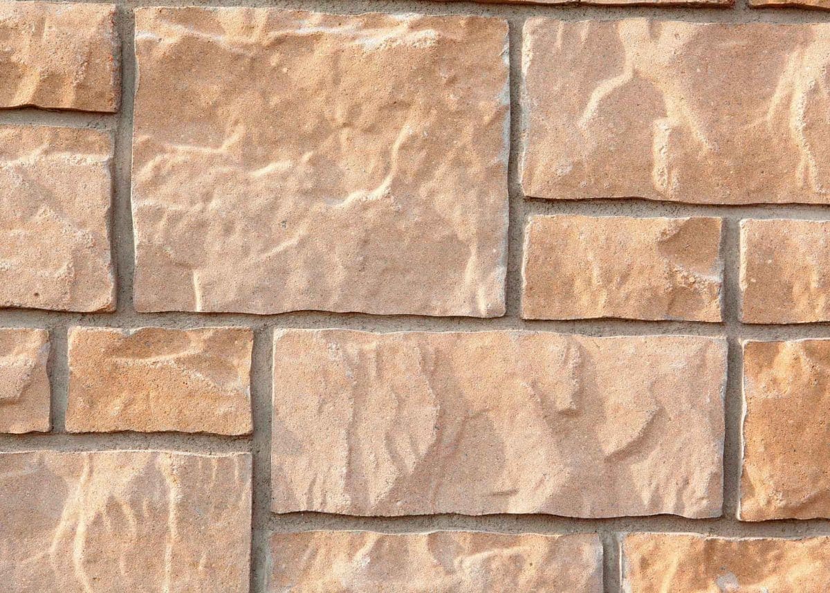
Manufactured Stone Veneer Proves its Curb Appeal, Tops List in Cost Vs. Value Study
It’s no secret that the overall value of a home begins with how people view it. Their initial impression is crucial whether they first spot it standing on the street, seeing it from a car window or getting a peek via photos online.
According to a REMODELING magazine report, what remodeling project significantly increases a home’s curb appeal while giving the homeowner an almost 100 percent return on investment when it comes to its cost versus the value it’ll ultimately fetch?
Contrary to long-held conceptions, it’s not a mid-range kitchen remodel, a window replacement, a deck addition, a vinyl siding addition, or even a minor kitchen renovation.
It’s manufactured stone veneer.
Citing the magazine’s 2019 “Cost vs. Value” study — which surveyed approximately 3,200 real estate pros about returns on 22 projects in 136 U.S. markets in 2018 — and despite rising material costs impacting overall returns, manufactured stone veneer came in at a whopping 94.9% average cost recouped. It was derived from an average job cost of $8,907 and an average resale value of $8,449. In entire study it was second only to garage door replacement, which came in slightly higher at 97.5%.
For manufactured stone veneer, it’s trend of performance that’s been consistent since it was added to the study in 2015. Since then, it’s been in the top three in return on investment (ROI) at a clip of 90 percent of greater each and every year.
“It’s huge,” said Rich Kelly, National Sales and Marketing Manager for Norse Building Products, a building materials company based in the Greater Chicago, Illinois area. Mr. Kelly is also the chair of NCMA’s Manufactured Stone Communications Subcommittee. “How many things can you invest in today and get back 97 percent? And that’s not putting the stone veneer on the whole house. That’s only 300 square feet on average.”
“The value of your house is all about curb appeal, and if you make a good choice of stone and a good color to go along with your siding — it’ll give you that type of boost.”
While the data shows that manufactured stone veneer is outperforming almost every other remodel project, it’s still not being presented as a no-brainer, cost-effective renovation option. But Kelly said, that’s swiftly changing.
“A lot of contractors are selling these exterior options at the kitchen table, at seven o’clock in the evening to a homeowner.” Kelly said. “If they don’t show stone veneer, they’re never going to get it. I tell the siding guys all the time, ‘you gotta have a stone sample in there.’ Because if you don’t offer it, maybe the next contractor coming in trying to close the deal comes in with stone and he closes it. Because he gave them a better option.”
“As we know, not many people are building castles today. Just a little bit of stone on the front goes a long way.”
Standard Specification for Adhered Concrete Masonry Units Released
ASTM standards are key in testing, specifying and assessing the basic materials and units used in masonry construction. Recently, the international standards organization released a new specification covering adhered concrete masonry units under the fixed designation of C1877- 18. Prior to this, no standard existed that provided minimum requirements for dry-cast concrete masonry units used in adhered veneer applications.
The scope of this standard:
This specification covers solid, dry-cast, concrete masonry units intended for use as an interior and exterior adhered veneer and are made from portland cement, water, and suitable mineral aggregates with or without the inclusion of other materials.
Among other details, it outlines terminology and includes specifications for materials and manufacture (normal weight and lightweight aggregates, cement, pigments and other constituents), physical requirements, dimensions, weights and areas, finish and appearance, methods of sampling and testing, and even compliance.
“Innovation sparks creativity and spurs growth, and the largest growth market in cladding systems in recent years is thin, adhered masonry veneers – providing the look and feel of full-bed masonry at a lower cost,” said Jason Thompson, Vice President of Engineering at the National Concrete Masonry Association (NCMA). “Untill now these systems have been limited to wet-cast concrete, clay, and natural stone. With the recent approval and publication of ASTM C1877, Standard Specification for Adhered Concrete Masonry Units, machine-made dry-cast adhered veneer units join the list of adhered masonry veneer cladding systems – providing new options and textures to ignite the next masonry design innovation.”
A copy of this standard can be obtained from ASTM.
Construction Study Says Concrete Masonry is as Affordable as Wood, Steel, Others
One of the biggest perceptions about building with concrete masonry is its cost — that other common building materials like wood, steel, precast concrete or even insulated concrete form (ICF), is a more cost-effective option.
A study, however, dispels this belief and firmly labels it a misconception.
According to the report — which was prepared by Water G.M. Schneider III, Ph. D., P.E., an agricultural and biological engineering professor at Pennsylvania State University in State College, Pennsylvania — not only does concrete masonry compete with these other materials, it was the most cost-effective option or within five percent of the lowest cost system.
It also provided superior fire safety and protection, resistance to mold growth, potential to withstand damage from wind and weather, as well as reduced cleanup costs and quick reoccupation.
The overall goal of the study was to develop a construction cost model that accurately evaluates the relative construction expense of building multi-family structures. In order to carry out its aim, Schneider and those involved utilized unbiased data regarding the overall initial cost of construction, which ensured an accurate comparison between each system.
The building model chosen? A four story multi-family residential structure with 25,000 square feet of building area per floor. Each prototype was designed in accordance with the 2015 International Building Code and International Energy Conservation Code.
The systems that were studied were as follows and all possessed a precast concrete floor system: light gage steel framing, load-bearing concrete masonry, precast concrete walls, and insulated concrete form (ICF) walls. The sixth and final system had ICF walls with an ICF floor system.
The three locations selected for the study were Dallas, Texas; Edgewater, New Jersey; and Towson, Maryland. For both Edgewater and Towson, accepted federal prevailing wage was used for labor rates while in Dallas a compilation wage rate based on R.S. Means was evaluated. To track the changing costs of construction materials, costs were evaluated in each city during December 2016, May 2017 and September 2018.
In Edgewater, concrete masonry proved to be the most cost-effective system during all three study periods. During the December 2016 period, concrete masonry and wood frame construction were within one percent, while in the May and September 2017 period concrete masonry was two percent and five percent less expensive than wood construction, respectively.
In Towson, concrete masonry was the most cost-effective system in the May 2017 period, three percent below the cost of wood. In the December 2016 and September 2017, concrete masonry was five percent and two percent more expensive than wood construction, respectively.
In Dallas, concrete masonry was the most affordable option in the May 2017 trial, with an overall cost that was four percent less than wood frame construction. In December 2016, it was four percent more expensive than wood, while in September the margin was six percent.
Following publication of the initial study, additional cities have been evaluated for relative cost using the same methodology. Evaluations are currently available for:
- Phoenix and Tuscon, Arizona
- Los Angeles, Sacramento, and San Jose, California
- Washington, DC
- Atlanta and Savannah, Georgia
- Chicago, Illinois
- Des Moines, Iowa
- Kansas City, Kansas
- Baltimore, Maryland
- Waltham, Massachusetts
- Omaha, Nebraska
- Mineola and Syracuse, New York
- Charlotte and Raleigh, North Carolina
- Toledo, Ohio
- Toronto, Ontario, Canada
- Lehigh Valley, Philadelphia, and Pittsburgh, Pennsylvania
- Columbia, South Carolina
- Knoxville, Tennessee
- Houston, Texas
- Richmond, Virginia
To read the study in its entirety, as well as updates, click here.
Concrete Masonry Checkoff Program Authorization Passes US Congress
[Herndon, VA – October 3, 2018] The U.S. Senate passed the Concrete Masonry Products Research, Education and Promotion Act, providing Congressional authorization for the concrete masonry products industry to develop its own commodity checkoff program to support needed industry initiatives. The concrete masonry products bill was included in H.R. 302 as part of the Federal Aviation Administration Reauthorization Act of 2018. Having already passed the House of Representatives, it now goes to President Trump, who is expected to sign before October 7, 2018.
“This is a great day for our industry,” said Major Ogilvie of CEMEX USA, national chair of the concrete masonry checkoff initiative since 2010. “We demonstrated a level of perseverance on this initiative that is only matched by the resilience of the products that we manufacture. By standing together, we will not only strengthen our industry, but our communities. We applaud the members of Congress for recognizing that the small businesses in our industry can accomplish even greater things together if we can more effectively pool our resources to promote ourselves.”
“Our work is just beginning,” said National Concrete Masonry Association Chairman of the Board, Kent Waide of Ruby Concrete. “Congress did not create a concrete masonry checkoff program, they only authorized it. Our entire industry will now begin the earnest discussions about how we develop a program that is meaningful to concrete block manufacturers of all kinds – those large and small, those in all regions of the U.S., and those with all kinds of local market interests. We will present the value proposition to rationalize an increased investment to collectively promote the value of concrete masonry systems.”
An industry referendum on program creation would likely occur in mid-to-late 2019, with every company that manufactures concrete masonry products being provided the opportunity to vote.
Numerous commodity checkoff programs already exist. Most of these programs relate to agricultural products under the management of the U.S. Department of Agriculture (USDA). The U.S. Department of Energy (DOE) oversees two such programs: propane and heating oil. Concrete masonry products would be the second such program related to construction products, the other being softwood lumber under USDA, and the first under the Department of Commerce.
Ogilvie expressed pride in the manner in which the advocacy effort was conducted. “Manufacturers and contractors in our industry invested a lot of time and energy to get to know their representatives and to share the impact of their businesses on local communities. We visited hundreds of congressional offices, secured nearly 300 bi-partisan co-sponsors when we were a stand-alone bill, and we were frequently praised on Capitol Hill for doing this the ‘right way’.” Ogilvie also praised the hard work of the bill sponsors who worked within a bipartisan approach to figure out how to move the legislation in a challenging environment. Representatives, Brett Guthrie (R-KY), Kathy Castor (D-FL), Senators, Roy Blunt (R-MO) and Bill Nelson (D-FL) have each acted as bill sponsors for the last three congressional terms.
NCMA President Robert Thomas maintains that the real winner through this congressional action is the general public. “People in this country deserve to live, work, shop, and learn in buildings that are resilient and durable. If we are successful, there will be more structures locally sourced, manufactured and constructed, creating more American jobs. These structures will be thoughtfully built with “strength,” resulting in more fire-resistant, energy-efficient, and cost-effective buildings that do not rot, burn, or decay.”
Another notable inclusion in the FAA reauthorization was the Disaster Recovery Reform Act, which represents an unprecedented shift in disaster resilience policy in the U.S. NCMA is an active partner in the BuildStrong Coalition advocating for enhanced pre-disaster mitigation funding and applauds Congress for recognizing that building decisions matter! In particular, NCMA compliments its concrete masonry checkoff bill sponsors who continue to be significant leaders on resilience legislation.
For more information about the concrete masonry products checkoff initiative and for future updates, visit www.cmucheckoff.com.
###

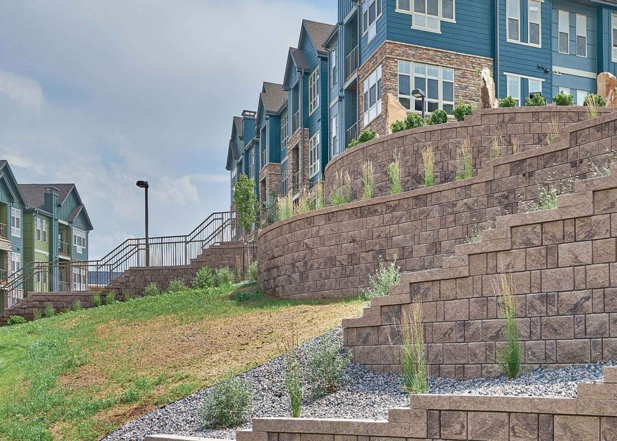
SRW History Articles Series: SRW Design

SRW Design:
At the end of this article, participants will be able to:
- Understand how masonry gravity segmental retaining walls are detailed and how they differ from mechanically stabilized earth (MSE) walls with a structural face of concrete masonry blocks (SRW). Describe bearing capacity, soil base and embedment, and the affect of slope on them.
- Approach the design of multi-depth and multi-tiered walls, especially for slope-restricted sites using segmental retaining wall (SRW) concrete blocks.
- Understand the requirements of mechanically stabilized earth walls, and the approach to soil stability.
It is estimated that about 50 percent of all segmental retaining wall (SRW) units are sold through retail outlets for smaller, gravity wall applications—walls that do not rely on internal soil reinforcement. The characteristics and design of some of the most common segmental retaining walls used by the construction industry vary depending on the site conditions and wall geometry.
Retaining walls are designed to resist the soil and surcharge loads supported by the system. Designing a retaining wall involves balancing the resisting forces with the driving forces to create a stable mass with a margin of safety against failure. When designing a segmental retaining wall, designers should follow established Concrete Masonry & Hardscapes Association (CMHA) or American Association of State Highway and Transportation Officials’ (AASHTO) methodologies.
CMHA vs. AASHTO
While AASHTO requirements are more conservative than CMHA’s, the two are similar. There are some key differences between the two:
- Minimum Geogrid Length:
CMHA 4ft (1.2 m) or 0.6H whichever is greater
AASHTO 8ft (2.4 m) or 0.7H whichever is greater
AASHTO specifications based the minimum 8 foot (2.4m) length on experience and ability to get construction equipment in behind the wall to compact the soil. The 0.7H was also based on experience with steel reinforcing. CMHA designs are based on geogrid reinforcing with 100 percent coverage (better pullout capacity), thus the 0.6H has worked well for common design scenarios.
- Load on the Reinforcement, TMAX While CMHA always uses the Coulomb Earth Pressures approach, factoring the slope, wall friction and wall batter into the equation, thus reducing the load (Tmax) in the reinforcing layers compared with an AASHTO design that only uses Coulomb Earth Pressures for walls above 10˚ face batter and Rankine Earth Pressures below 10˚.Internal Compound Stability Analysis ExampleReinforced Fill Soil Types. CMHA allows for the use of materials having a maximum 35 percent passing the #200 (75 µm) sieve, and suggests that materials with greater percentage of fines may be used when a geotechnical engineer is involved. AASHTO restricts use of materials for the reinforced fill zone and requires granular materials with less than 15 percent passing the #200 (75 µm) sieve.
- Connection
CMHA uses the maximum geogrid load (Tmax) with factor of safety of 1.5 and compares this to the Peak
Connection Capacity between the geosynthetic and SRW Unit.
AASHTO also uses a factor of safety of 1.5 on Tmax; however, AASHTO also requires an additional reduction factor to be applied to the Peak Connection Capacity that is derived from long-term, sustained load connection testing. This is a very conservative assumption and not justified by performance or data from instrumented structures that indicates the conservatism inherent in current SRW design methods.
Over turning
CMHA has suggested a factor of safety of over turning (ability of the structure to resist rotating for ward) of 1.5 for gravity walls and 2.0 for MSE structures. In AASHTO LRFD (2012), eccentricity is specified (the location of the load resultant with respect to the center of the footing, L) as e/L < 0.33. The resultant should be within the middle 1/3 of the base. e/L yields about the same design as a factor of safety of 2 would using the CMHA methodology.
Seismic Design
Both CMHA and AASHTO methods use the Mononobe-Okabe methods for pseudo static design. Both also assume the total dynamic stress is evenly distributed over all the layers of reinforcing. CMHA, however, promotes the use of seismic design in seismically active zones, where AASHTO does not consider seismic design mandatory in zones 1-3 unless liquefaction induced lateral spreading seismically induced slope failure, due to the presence of sensitive
Forces and geometry for external stability analysis of conventional SRWs clays that lose strength during seismic shaking, may impact the stability of the wall or if the wall supports another structure that is required by code or specification to be designed for seismic loading and poor seismic performance could impact the structure.
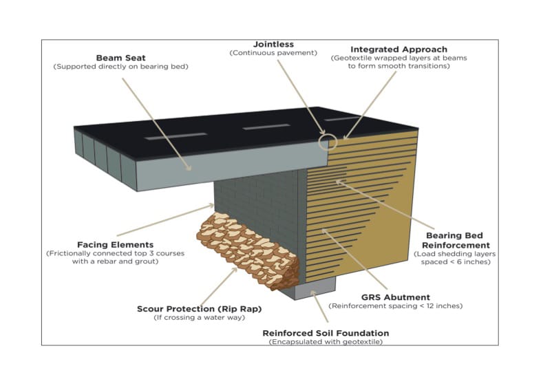
GRS-IBS: Solutions to Bridge Construction Challenges
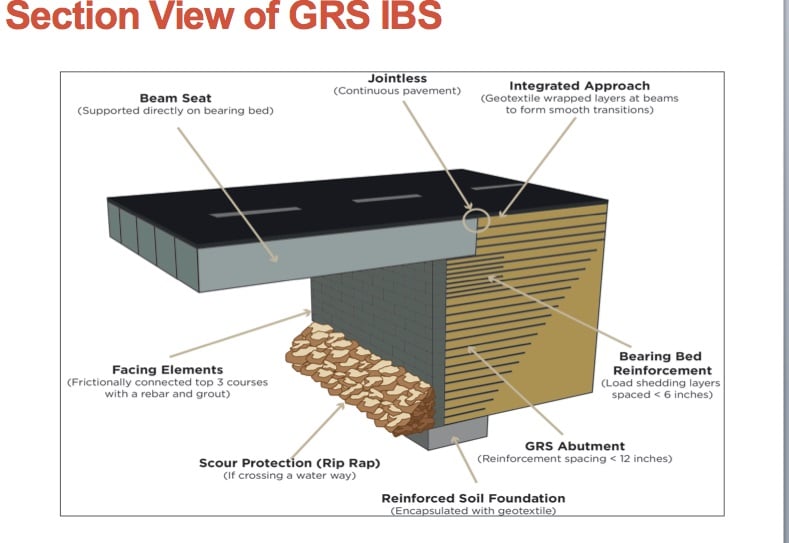
The Federal Highway Administration (FHWA) finds the Geosynthetic Reinforced Soil Integrated Bridge System (GRS-IBS) is becoming an economical and ease-of-construction alternative to some traditional bridge systems.
Despite many new bridges and replacement projects, American bridge infrastructure is aging and seriously deficient. Virtually every state in the nation is faced with the task of replacing unsafe bridges that have outlived their design life.
According to the American Road and Transportation Builders Association, there are nearly 204 million daily crossings on 58,495 structurally deteriorating U.S. bridges in need of repair. By 2023, one in ten bridges will be 65 years or older, despite an average design life of 50 years.
The replacement cost of spent bridges nationwide is estimated to be more than $75 billion, reports Transportation for America. States are addressing costly bridge replacement projects as best they can.
The GRS-IBS is a fairly new and innovative bridge design developed by the FHWA. GRS-IBS has emerged as a cost-effective solution for single-span bridge construction, one that is relatively quick to construct.
Rather than relying on a conventional bridge support system of piles beneath the bridge, GRS-IBS uses alternating layers of compacted granular fill with layers of geotextile reinforcement. Concrete masonry units (CMUs) or segmental retaining wall (SRW) systems and materials offer durable and attractive facing to the reinforced bridge abutments. There is no need to pour concrete footings or other concrete components, which can add time to a project. Eliminating forms, rebar and curing all help speed up construction. In place of driven piles and poured concrete, the bridge structure is built directly on a geosynthetic reinforced subsoil mass.
In some instances, GRS-IBS can be used for repair and rehabilitation of existing 7bridge structures. Existing bridge abutment structures can remain in place and contribute additional stability to the newer system. The existing foundations can also play a role as scour protection for the new abutments.
The abutments for the GRS-IBS are constructed on top of the subsoil mass by compacting granular backfill in thin layers and alternating it with closely spaced, thin layers of geosynthetic reinforcement. The geosynthetic reinforcement layers are placed 12 in (0.31 m) or less apart, according to the FHWA, but 8 in (0.20 m) is the most common separation. At a minimum, there should be five layers of geosynthetic at the bearing base.
Backfill and geosynthetic reinforcement together create a substructure that holds itself up. That means facing blocks are not burdened with the need to hold back the large mass of soil. The facing element is not a structural component of the system and serves only as a form for compaction and an attractive façade that protects the granular fill from weathering. According to FHWA reports, the system only requires friction between units to connect the modular block face to the backup reinforcements. That differentiates this system from most mechanically stabilized earth structures. In this system, the geosynthetic is extended to the face wall and the two securely tied together through friction.
Several types of CMU are commonly used as facing materials in this system. Solid-face, hollow-core and corner block in standard dimensions are most often recommended. There are also a number of SRW block configurations ideally suited to the GRS-IBS.
Backfill should be crushed, hard and durable particles and fragments of gravel and free of organic material. Specifying the correct backfill is important, as it is a major structural component of the abutment. It must be compacted to a minimum 95 percent of maximum dry density of a standard proctor. Locally available aggregates meeting material specifications are the most cost-effective choice for GRS construction.
Geosynthetic materials are available in various strengths for abutment construction. GRS-IBS typically use a biaxial woven polypropylene geotextile. It is attractive due to its favorable cost, ease of installation and compatibility with the connection between block facing and the GRS mass, reports FHWA.
The system is ideally suited to small, single-span bridges with spans of up to 140 ft (42.6 m). It is estimated that the typical wall face area per GRS-IBS project is between 2,000 sf (185.8 sq m) and 4,000 sf (371.6 sq m).
Many attractive qualities
Once the GRS concept was introduced for use in bridges, it immediately caught the attention of states faced with the most pressing bridge deterioration problems. One of the system’s advantages is its flexible design approach. In the event of unforeseen site conditions or bad weather, GRS-IBS can be successfully modified in the field.
Other advantages stem from working with readily available materials and equipment, making these bridges faster to build. As a result, there are shorter travel disruptions and increased worker productivity and safety.
CMUs and SRWs contribute to the cost savings for these bridge projects: The materials are easy to transport, can be custom manufactured, are easily placed without heavy equipment, and locally produced.
The GRS-IBSt of the bridge construction blends the roadway seamlessly into the superstructure of the bridge and support. This alleviates the typical bump at end crossings, where the bridge meets the road. The bump results from differential settling of the road. The bridge portion itself generally does not settle much. But in standard bridges, as time passes and roads settle, the bump is created. With the GRS-IBS this situation is avoided because the road approach slab, the abutment and the bridge beams are meshed together and operate as a single monolithic structure. The result is that bridge and road settle together.
There are 600,000 bridges in the United States. Three-fourths of those could use GRS-IBS technology. States facing major amounts of bridge reconstruction are enticed by the economics of GRB-IBS. In addition to efficiencies in time and materials, the system can be installed at significantly lower construction costs. Savings of 25-60% have been reported in the existing projects and can generally be expected. There are few environmental impacts, thus this is a favored sustainable bridge construction approach with little in the way of maintenance required.
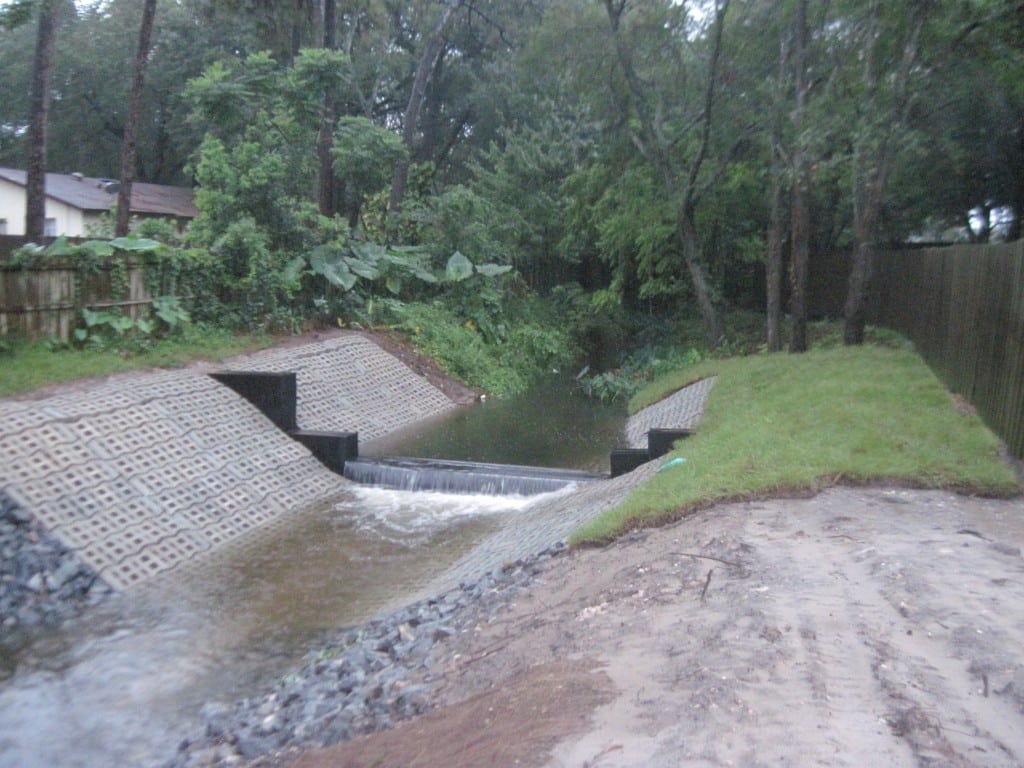
Revitalization of a Runoff Canal With ACBs
With neighborhoods being threatened with flooding and erosion, Florida Department of Transportation (FDOT) used articulating concrete blocks to redirect stormwater runoff.
Even in sunny Orlando, FL, the rain comes, and when it does, flooding is a primary concern. Runoff from roads and highways flows rapidly through ditches such as State Road 434 Out Road Canal, installed years ago by FDOT. Florida has been regulating stormwater discharge and management since the 1980s with the intention of protecting its surface waters.
The Florida Department of Environmental Protection (FDEP), regional water management districts and local governments all have oversight responsibilities for stormwater runoff. FDEP requires 80 to 95 percent reduction in the annual loads of pollutants from rainwater discharge. Meanwhile, the City of Orlando maintains its streets to keep them clean, safe and in good repair. Orlando also ensures that the drainage facilities perform as intended and that receiving water bodies meet state and federal water quality standards.
The aging drainage ditch that served a portion of State Road 434 had been eroding over time, according to Dale Mudrak, project engineer with Gregori Construction and Engineering.
Local properties in the residential neighborhoods where the water runs through were threatened with erosion and potential flooding. In order to prevent further damage, FDOT applied to the regional water district for a permit to make improvements on the 434 Canal drainage ditch, which serves as a conveyance system to channel runoff brought in from the State Road, two adjacent subdivisions and a lake at its head. That runoff ultimately flows into Little Wekiva River and through Wekiva River Buffer Conservation Area, with its fragile wetlands that are often flooded in the rainy season. The local water district officials recognized the need for improvements to the outdated infrastructure. However, the contractor was required to include vegetation along the canal bank and maintain the plants for one year to mitigate the loss of natural vegetation during construction.
Like much of Florida, the canal banks were mostly sand, so any rapid flow in the drainage canal would lead to erosion. Flowing stormwater added to the canal from the adjacent residential properties caused the erosion to increase, especially in areas with no vegetation or where the area lacks stabilization.
ACBs meet site challenges
Ready mixed concrete was first considered for the project, but there were site restrictions that could not be met with that solution. Access to the drainage ditch near the two subdivisions was restricted; too small to get a ready mixed truck on-site. In addition, the FDOT was seeking a sustainable solution allowing plants to grow in the revetment area. “So they went with articulating concrete block (ACBs) instead of ready mix,” Mudrak said.
The proprietary ACBs selected for this 25,000 sf (2322 sq m) project were 6 in units (152 mm). They were installed as mats, which required a crane for placement. Mudrak says the contractor got permission from two homeowners to bring in a crane between their properties, and the clearance was so tight that the crane’s retractable wheels had to be withdrawn.
Steel sheet piles were used across the canal to slow down the speed of the runoff. When the velocity of the stormwater is decreased, particles in it have time to settle out on the bottom, helping to clear the water. “The ACBs are extremely important in periods of high flow after a storm event as water will flow around or over the sheeting weirs, actually increasing water speed,” says Mudrak. When that happens, the ACBs will keep the bottoms and sides of the canal from eroding away.
The Florida Administrative Code’s Water Resource Implementation Rule sets design criteria for stormwater systems. In situations like State Road 434, where the runoff discharges into the conservation area of Wekiva River, the rules require a 95 percent reduction in pollutant loads. Water quality was a big issue for the drainage project and one of the critical factors for why FDOT chose ACBs, according to Mudrak.
Technically ACBs were considered a conveyance system, not a treatment system on the canal but actually accomplish some of both. The combination of the steel weirs and extensive ACB mats offer some water treatment benefits. By slowing down the water flow with the steel sheeting, there is less erosion and some of the sediment carried in the runoff has time to settle to the bottom.
As for treatment, the ACBs allow vegetation to grow in the open cells along the canal’s banks. The vegetation then absorbs nutrients from the water which cleans it. The open cells on the bottom of the canal allow sand to settle and keep it from continuing down stream. Once established, the natural vegetation can hide the ACBs that are stabilizing the slopes. The life expectancy of this drainage conveyance system, with its treatment qualities, is 50 years.
“We see ACBs as one of the solutions to erosion and slope stabilization issues. They are an engineered product and in many cases provide better performance than natural products. We expect to see continued lower overall cost utilizing ACBs compared to other products which is due to limited amounts of natural resources and the increased cost of trucking them. The quality of the ACBs combined with design flexibility and production sizes—both thickness and mat size—make it preferred by owners, designers and contractors,” says project engineer Mudrak.
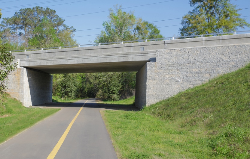
Florida Manages Orange Avenue Bridge With GRS-IBS
An old, deteriorating trestle bridge above an historic trail in Tallahassee, FL, was scheduled for replacement. Orange Avenue Bridge sits above the intersecting bike and pedestrian trail portions of St. Marks Trail. Replacing the 60 ft (18.3 m) bridge would be straightforward in most circumstances. But this short-span bridge construction project faced a number of challenges.
With a bike path and a pedestrian trail directly below the bridge, there was little room to excavate support walls. And timing was critical, as the road serves an elementary school and is in frequent use most of the year. In addition, the Florida Department of Transportation (FDOT) had a limited budget for the replacement project.
Once school was out and summer recess underway, the road was closed so construction could begin. The old bridge was removed and excavation for the new support walls began. A proprietary concrete block retaining wall system was specified for its near vertical batter, which helped alleviate the space restriction issue and also allowed for a much wider passageway for the trail below the bridge.
Speeding up construction time through completion was a high priority for this project. The concrete block face walls are dry stacked, and as a result, the abutment walls were rapidly erected and ready to support the superstructure. With dry-stacking there was no cure time required, meaning that the abutment wall construction was not interrupted at various courses and so installation progressed ahead of schedule. The abutment walls were 18 ftt high (5.5 m), with acute angles that necessitated special cuts in the block, along with rebar reinforcements at the corners and on the sides. To prevent the corners from separating, block cores were filled with grout, from top to bottom. The Orange Avenue Bridge opened to traffic 23 days ahead of schedule.
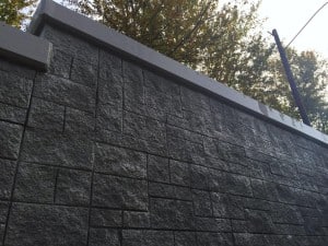
Concrete Masonry Provides Solution for Sound Wall
You often see noise barriers or sound barriers (as referenced in other parts of the country) that line busy roadways constructed from precast concrete panels or tilt-up concrete walls. However, the Washington State Department of Transportation (WSDOT) required something completely different for this stretch of Route 167 in the corridor between Tacoma and Seattle.
This nearly two-mile-long sound barrier is constructed of concrete masonry units (CMU), something that Jim Reynolds, the general manager and safety director of out of Marysville, Washington, hasn’t seen constructed for at least 20 years on the west side of the Cascades.
Not only do the CMU blocks meet all of the WSDOT requirements, but their use solved some other issues as well. “The soils in the area are just too soft for tilt-up concrete walls,” Reynolds said, “and to use them they would have to dig down so much to install footings for precast panels.” He then explained that in order to do that, the general contractor Atkinson Construction of Renton, Washington, would have shut down lanes of traffic on the busy freeway disrupting the commute between Ellingson Road and 15th Street SW in Algona. “They would have been forced to bring in a crane for installation. Space is limited in the area” said Reynolds. He went on to say that they could have worked on the project at night, but the traffic interruptions, construction lights and noise would have disrupted the very neighborhoods they were building the wall to protect.
A Pattern to Prevent Graffiti
Another major factor for WSDOT is the prolific graffiti in the area. “Planners wanted to utilize surfaces that discourage graffiti, and materials that can be easily painted over in the event the wall does get tagged” according to Reynolds. “So we proposed a 6-inch wide double-sided split face block.” R&D Masonry recommended the texture and the use of an Ashlar pattern, both of which would discourage vandalism.
Don Kenney, president of R&D Masonry, said “Ashlar bond jobs constructed out of CMU break up the surface and provide more joints and more relief, which makes tagging less desirable.” WSDOT was very happy with the solutions, and wanted even more features such as raked joints between the blocks that CMUs were able to incorporate according to Kenney.
Larry Smith, the project manager from Atkinson, stressed that teamwork among all of the groups involved in the project helped make it a success. “Everyone worked together to ensure the state’s standard plan was met. We came up with a workable design and build plan. We worked out the pattern. The team at R&D were engaged from the start, they built wall mock-ups to present to WSDOT for approval.”
Sharif Shaklawun, WSDOT project engineer, said “The project looks great! We are getting positive feedback. The pattern and raked joints alleviate the graffiti concern.”
Cost-savings and Labor Advantages
Shaklawun went on to say that some people in the community voiced concern that such an aesthetically pleasing wall constructed from CMUs must cost taxpayers more than conventional precast panels. “We explained the design/build process and that the project cost was comparable to other materials. And since we didn’t have to disrupt traffic to install the wall, it was a good solution.”
Reynolds explained that the minimal excavation, the fewer footings and the reduced labor made this an efficient solution. “We were able to complete the project much more quickly.”
Smith also addressed the cost issue. “There’s an economic benefit of using local labor on site to build the wall. Fabricated walls are made somewhere else, they don’t pay prevailing wage or stimulate the local economy,” he said.
Construction Strategy
Atkinson dug a footing every 14 feet (4.3 m) for pilasters constructed from 16-inch square column block filled with 6,000 psi (41.3 kPa) grout, rebar and lateral ties. The CMUs manufactured by local producer were placed on a 2 ft (61 cm) deep leveling pad made of free-draining aggregate. “We went with gray block that was stained washington gray” said Reynolds.
The wall sections vary from 8 to 20 ft (2 to 6 m) tall. “We built scaffolds on both sides of the wall and laid the block in sections. I gave each of the guys a laminated card that showed them the repeating six-piece pattern (since this was a complicated pattern),” said Reynolds. Eight in (203 mm) tall blocks used as bond beams were placed every 32 in (81.2 cm) vertically and reinforced the wall sections. The total project was made up of 190,000 units. “We had a crew of 30 to 40 mason contractors lay about 4,000 blocks a day.” R&D was on the job working six to seven days a week to meet the schedule.
Tom Young of the Northwest Concrete Masonry Association thinks the noise wall (sound wall) market is a perfect extension for CMU manufacturers in the Northwest. “We’ve worked hard to convince general contractors in the area that masonry has several advantages,” he said. “The association has produced standard design plans that meet the state’s requirements, and we’ve put preliminary cost figures together to demonstrate the cost effectiveness of masonry.” Tom also knows the importance of promoting the aesthetics of concrete masonry walls. “I went to California, the center of the CMU noise wall universe, and took lots of pictures of walls to show to planners in our state the many design possibilities.”
The Algona wall was finished off with a cap constructed of 10 in (245 mm) wide hollow blocks that overhang the wall by 2 in (50.8 mm) on each side. “Originally they were going to pour the cap in place, but they couldn’t keep up with us,” said Reynolds. Once in place, the cap blocks were filled with grout and rounded on top. “We even scored the columns by grinding false joints to match the pattern. I know WSDOT was very pleased with the end result.” Reynolds is confident that planners will build more walls in the area using the same product.
Reynolds indicated that the unexpected element of the project was the reaction by the community. “We actually got calls from people who live in the area, they would see our construction sign. They called to thank us for building such a beautiful wall in their neighborhood.” The beauty of this new wall is that not only has it greatly reduced traffic noise for residents, businesses and churches in Algona, but that it reduced the impact on the environment, avoided disruption to traffic and saved taxpayer money.
“Everyone from the people at the transportation department to commuters and the people who live in the area love the look. It really stands out, and gives our industry great exposure” said Kenney.
Photos and graphics courtesy of R&D Masonry, Inc.